The Role of Fiber Optic Attenuator in Networks
A Fiber Optic Attenuator is an essential passive device used in fiber optic communication systems to reduce the power level of an optical signal. In many scenarios, the signal generated by a transmitter is too strong for the receiver, which can lead to saturation and distortion, ultimately causing high bit error rates and even damaging the receiver’s components. By precisely reducing the signal’s power without distorting its waveform, these components ensure that the optical power at the receiver end is within the optimal operational range. This precise control is critical for maintaining the integrity and reliability of the entire network. Consequently, understanding the function and application of attenuators is fundamental for network engineers and technicians aiming to design and maintain high-performance optical communication links. EPCOM provides a wide range of attenuators designed for various applications, ensuring optimal network performance and longevity.
Understanding the Need for a Fiber Optic Attenuator
In an ideal fiber optic system, the signal that leaves the transmitter would arrive at the receiver with just the right amount of power. However, reality is far more complex. The power of a light signal is influenced by numerous factors. For instance, in short-distance single-mode fiber applications, the laser transmitters used are often powerful enough for long-haul transmissions. When these powerful signals travel over a short link, they arrive at the receiver with excessive power. This is a common issue in Dense Wavelength Division Multiplexing (DWDM) systems, where multiple optical signals are multiplexed into a single fiber. Without proper management, this excess power can overwhelm the photodetector in the receiver.
An optical receiver has a specific dynamic range—a range of power levels it can accurately detect. If the incoming signal power is below this range, the receiver won’t be able to distinguish the signal from noise. Conversely, if the signal power exceeds this range, the receiver becomes saturated. Think of it like someone shouting directly into your ear; the sound is so loud that it becomes distorted and unintelligible. A fiber optic attenuator acts like a volume control, turning down the “shout” to a comfortable listening level for the receiver. This process is crucial for achieving a low bit error rate (BER), which is a key indicator of network performance. Furthermore, by preventing receiver overload, attenuators play a vital role in extending the lifespan of sensitive network components.
How Does a Fiber Optic Attenuator Work?
A Fiber Optic Attenuator operates on simple yet effective principles to reduce optical power. The reduction, or attenuation, is achieved primarily through three methods: absorption, reflection, or scattering of the light signal. Unlike other components that might filter specific wavelengths, a high-quality attenuator reduces power consistently across a wide range of wavelengths. This ensures the integrity of the signal is maintained.
Several techniques are employed to achieve this attenuation:
- Doped Fiber Technology: This is a common method where a section of the optical fiber is “doped” with metal ions, such as erbium. These ions absorb the light energy as it passes through, converting it into a small amount of heat. The level of attenuation can be precisely controlled by adjusting the concentration of these ions and the length of the doped fiber. This technique is known for its reliability and stability.
- Air Gap Technique: This method involves creating a small, precise gap between two fiber connectors. As the light exits one fiber and travels through the air gap to enter the next, a portion of the light is reflected back and scattered due to the change in the refractive index between the glass fiber and the air. This results in a reduction of the transmitted power. The amount of attenuation can be adjusted by changing the length of this gap.
- Microbends: Creating small, controlled bends in the fiber can also induce attenuation. These microbends cause some of the light traveling within the fiber core to strike the core-cladding boundary at an angle that allows it to escape, thus reducing the power of the signal that continues down the fiber.
The choice of technique depends on the type of attenuator and the specific application requirements. Regardless of the method, the goal remains the same: to achieve a precise and stable reduction in signal power without compromising the quality of the data being transmitted. This precision is why selecting a high-quality attenuator from a trusted supplier like EPCOM is critical for network reliability.
Exploring Different Types of Fiber Optic Attenuators
Fiber Optic Attenuators are not a one-size-fits-all solution. They come in various forms, each designed to meet specific needs within a network’s architecture. The most fundamental distinction is between fixed and variable attenuators. From there, they can be further categorized based on their form factor and the type of connector they use. Understanding these differences is key to selecting the right component for your application.
Fixed vs. Variable Fiber Optic Attenuators
The primary classification of attenuators is based on their ability to adjust the attenuation level.
Fixed Fiber Optic Attenuators: As their name implies, these devices have a predetermined, unchangeable attenuation value, such as 3dB, 5dB, or 10dB. They are used in applications where the required level of power reduction is known and constant. Fixed attenuators are valued for their simplicity, stability, and cost-effectiveness. They are typically installed once and left in place, making them ideal for permanent links in a network. They come in various connector styles, such as LC, SC, ST, and FC, to match the existing network connections seamlessly.
Variable Fiber Optic Attenuators (VOAs): These attenuators offer the flexibility to adjust the level of attenuation. This is particularly useful in environments where the optimal power level is not known beforehand, such as in laboratory testing, system prototyping, or in networks where conditions might change over time. VOAs allow technicians to fine-tune the signal power to find the perfect balance for optimal performance. They are generally more complex and expensive than their fixed counterparts but provide invaluable flexibility for dynamic applications and troubleshooting scenarios.
Plug-Type and In-Line Fiber Optic Attenuators
Beyond the fixed versus variable distinction, the physical design or form factor is another important characteristic.
Plug-Type Attenuators: This is one of the most common types. It looks like a standard fiber optic connector bulkhead adapter but with a male plug on one end and a female socket on the other. It’s designed to be plugged directly into a receiver port or an adapter in a patch panel. The male end connects to the receiver or panel, and the patch cord then plugs into the female end. This design is compact, easy to install, and available for all common connector types like LC, SC, ST, and FC.
In-Line Attenuators: An in-line attenuator is integrated directly into a fiber optic patch cord. It resembles a small cylinder or box spliced into the cable. This type is useful when space on the patch panel is limited or when attenuation is needed somewhere along a cable run rather than at the termination point. While less common than plug-type attenuators, they provide a clean solution for specific architectural needs. To maintain network integrity, it’s crucial to use high-quality patch cords like the MPO/MTP Patch Cord, which are designed for high-density applications and ensure minimal signal loss before the point of attenuation.
Key Parameters and Specifications of a Fiber Optic Attenuator
When selecting a fiber optic attenuator, several key specifications must be considered to ensure it meets the requirements of your network. These parameters define the performance and reliability of the attenuator. Overlooking these details can lead to suboptimal network performance or even damage to components.
Crucial Specifications for Any Fiber Optic Attenuator
- Attenuation Level (dB): This is the most fundamental specification. It indicates how much the attenuator reduces the signal power, measured in decibels (dB). For fixed attenuators, this is a single value (e.g., 5 dB). For variable attenuators, it’s a range (e.g., 0-20 dB).
- Wavelength Range (nm): Optical components are designed to operate optimally within specific wavelength windows. Common windows for telecommunications are 1310 nm and 1550 nm for single-mode fiber and 850 nm for multimode fiber. The attenuator must be specified for the wavelength(s) being used in the system to ensure it provides accurate attenuation without introducing other issues.
- Return Loss (dB): Return loss, or back reflection, measures the amount of light that is reflected back towards the source. A high return loss value is desirable, as it indicates that less light is being reflected. Reflected light can cause instability in the laser source and increase the bit error rate. A good attenuator will have a high return loss (typically >50 dB).
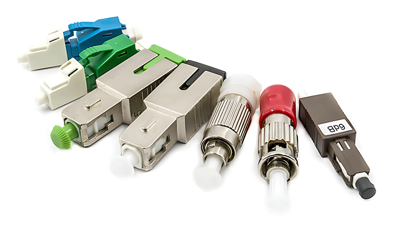
- Connector Type: The attenuator’s connectors must match the cables and equipment in your network. Common types include LC, SC, ST, and FC. Using the wrong connector type requires an adapter, which can introduce additional signal loss and potential points of failure. For components like adapters, it’s essential to use reliable products such as the ST Fiber Optic Adaptor to ensure a secure and low-loss connection.
- Polarization Dependent Loss (PDL): This specification is relevant for high-speed and analog transmission systems. It measures the variation in attenuation as the polarization state of the light changes. A low PDL is crucial for ensuring stable performance, as it means the attenuation level remains consistent regardless of the light’s polarization.
Comparison of Common Fiber Optic Attenuator Types
| Feature | Fixed Attenuator | Variable Attenuator (VOA) |
|---|---|---|
| Attenuation Control | Pre-set, unchangeable value | Adjustable over a specified range |
| Primary Use Case | Permanent installation in stable networks | Testing, troubleshooting, dynamic networks |
| Complexity | Simple, passive device | More complex, may involve mechanical parts |
| Cost | Lower | Higher |
| Reliability | Very high due to lack of moving parts | High, but moving parts can be a potential failure point |
Applications: Where Are Fiber Optic Attenuators Used?
The application of fiber optic attenuators spans across various domains of optical networking. Their fundamental purpose of controlling signal power makes them indispensable in several key areas. From telecommunications and data centers to test and measurement labs, attenuators ensure that optical systems operate reliably and efficiently.
Telecommunication Networks
In long-haul and metro telecommunication networks, erbium-doped fiber amplifiers (EDFAs) are used to boost the signal strength to cover vast distances. While these amplifiers are essential, they can also produce an output power that is too high for the subsequent stages of the network or for the final receiver. A Fiber Optic Attenuator is often placed after an amplifier to bring the signal power down to a safe and optimal level. This is particularly important in DWDM systems where many channels, each with its own power level, must be balanced to ensure equal performance across all channels.
CATV and Analog Systems
Cable television (CATV) networks were one of the early adopters of fiber optic technology. These systems often use analog transmission, which is highly sensitive to the signal-to-noise ratio (SNR). The optical power level directly impacts the carrier-to-noise ratio (CNR), a key performance metric. Using attenuators allows network designers to precisely control the power levels delivered to different nodes in the network. This ensures that all subscribers receive a clear, high-quality signal, regardless of their distance from the headend.
Data Centers and Enterprise Networks
Modern data centers rely heavily on high-speed fiber optic links to connect servers, switches, and storage arrays. While many of these links are relatively short, the transceivers used are often capable of transmitting over much longer distances. This mismatch can result in receiver overload. A plug-type fiber optic attenuator is a simple and effective solution to this problem. By installing an attenuator directly at the receiver port of a switch or server, data center technicians can ensure reliable, error-free communication, which is critical for the performance of applications and services hosted in the data center.
Test and Measurement Setups: A Vital Role for the Fiber Optic Attenuator
In laboratory and field testing scenarios, a variable fiber optic attenuator is an invaluable tool. It allows engineers to simulate the signal loss that would occur over different lengths of fiber. This is essential for determining the power budget and margin of a system. By gradually increasing the attenuation, engineers can find the “cliff” where the system fails, thereby identifying the limits of its performance. This process, known as bit-error-rate testing (BERT), is fundamental to qualifying network equipment and certifying that a newly installed link meets its design specifications. It helps in understanding how a system will behave under various real-world conditions.
Best Practices for Installation and Maintenance
Proper installation and maintenance are crucial for ensuring the long-term reliability of any network component, and fiber optic attenuators are no exception. While they are passive devices and generally very reliable, following best practices can prevent common issues that lead to network downtime. The most critical aspect of handling any fiber optic component is cleanliness.
The Importance of Cleanliness for Any Fiber Optic Attenuator
The core of an optical fiber is incredibly small—only 9 micrometers in diameter for single-mode fiber. A tiny speck of dust, oil from a fingerprint, or other contaminant can easily block a significant portion of the light, leading to high signal loss, increased back reflection, and poor network performance. This is why cleaning and inspection are paramount.
Before installing any attenuator or connecting any fiber cable, it is essential to inspect the connector end-faces with a fiber scope. If any contamination is found, it must be cleaned. For this task, specialized tools are required. Using a tool like the Fiber Optic Cassette Cleaner is a highly effective way to ensure that connector end-faces are pristine before mating. This simple step can prevent a wide range of hard-to-diagnose network problems. It’s a foundational practice that is emphasized by industry bodies like the Fiber Optic Association (FOA), which provides extensive resources on proper fiber optic handling procedures.
Installation and Handling Tips
- Inspect and Clean: As mentioned, always inspect and clean both the male and female connectors before making a connection. This applies to the attenuator itself and the patch cord and equipment port it connects to.
- Use Dust Caps: Keep protective dust caps on all connectors and attenuators when they are not in use. This prevents dust and debris from settling on the sensitive end-faces.
- Avoid Over-tightening: When using screw-on connectors like FC or ST, do not over-tighten them. This can cause physical stress to the fiber and the connector ferrule, potentially damaging them.
- Mind the Bend Radius: Be careful not to bend the fiber optic patch cords too sharply near the attenuator. Exceeding the minimum bend radius can cause micro-cracks in the fiber, leading to signal loss and eventual failure.
- Document Everything: When an attenuator is installed, its location and dB value should be recorded in the network documentation. This information is invaluable for future troubleshooting and network upgrades.
By adhering to these best practices, network operators can ensure that their fiber optic attenuators perform as expected, contributing to a stable and reliable network infrastructure. This attention to detail is what separates a well-managed network from one that is plagued by intermittent and frustrating problems. High-quality components from a reputable supplier like EPCOM, combined with professional installation and maintenance practices, are the cornerstones of high-performance optical communication.
Conclusion: The Silent Guardian of Signal Integrity
The Fiber Optic Attenuator, though a small and often overlooked component, plays a profoundly important role in the world of optical communications. It is the silent guardian that protects sensitive receivers from the damaging effects of excessive power, ensuring that data flows accurately and reliably. By precisely controlling signal strength, attenuators enable network architects to build robust and flexible systems that can accommodate a wide range of equipment and transmission distances. Whether in a massive trans-oceanic telecommunication system or a short link within a data center, the fundamental principle remains the same: delivering the right amount of power is just as important as delivering the signal itself.
From the straightforward reliability of fixed attenuators to the diagnostic flexibility of variable models, there is a solution for every application. As network speeds continue to increase and the demand for bandwidth grows unabated, the need for precise signal management will only become more critical. Therefore, a thorough understanding of how, when, and where to use a fiber optic attenuator is an essential skill for any professional working with fiber optic technology. By choosing high-quality components from EPCOM and adhering to industry best practices for installation and maintenance, you can ensure your network operates at its peak performance, delivering the speed and reliability that modern applications demand. For more information on the physics behind light transmission in fiber optics, resources from academic institutions like MIT provide in-depth knowledge.