Fiber Optic Fusion Splicer: A Comprehensive Look
A Fiber Optic Fusion Splicer is an indispensable tool in the telecommunications industry, serving as the cornerstone for building and maintaining the high-speed data networks that power our modern world. In an age dominated by instant communication, streaming services, and the Internet of Things (IoT), the demand for faster and more reliable data transmission has never been greater. Fiber optic cables are the answer to this demand, offering unparalleled bandwidth and speed over vast distances. However, the effectiveness of these networks hinges on one critical process: creating a near-perfect connection between two fiber optic strands. This is precisely where fusion splicing excels. By precisely aligning and welding glass fibers together with an electric arc, this technology creates a permanent, low-loss joint that is stronger and more reliable than any mechanical connector. As a leading provider of telecommunications solutions, EPCOM is dedicated to supplying the highest quality equipment to ensure every splice is a successful one.
Principles Supported by the Fiber Optic Fusion Splicer
Before diving deep into the mechanics of a fiber optic fusion splicer, it’s essential to understand the technology it supports. Fiber optics represent a revolutionary method of transmitting information. Instead of sending electrical signals through copper wires, this technology converts data into pulses of light and sends them through incredibly thin strands of glass or plastic known as optical fibers. This method offers significant advantages, including higher bandwidth, greater speed, immunity to electromagnetic interference, and enhanced security. Consequently, fiber optics have become the backbone of global communication, from transoceanic cables connecting continents to the fiber-to-the-home (FTTH) networks that deliver high-speed internet to our doorsteps.
Fiber Cable Anatomy and Fusion Splicer Preparation
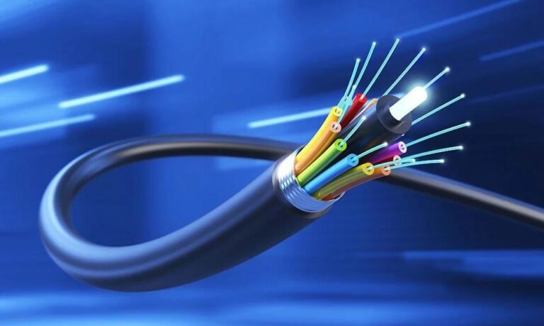
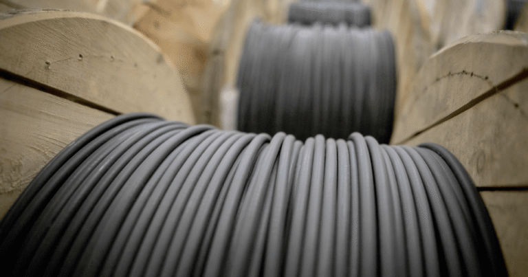
A fiber optic cable may seem simple, but it is a precisely engineered structure designed to protect the fragile glass fiber and guide light effectively. It primarily consists of three concentric layers:
- The Core: This is the central part of the fiber, made of ultra-pure silica glass, through which the light pulses travel. The diameter of the core is minuscule, typically ranging from 9 micrometers for single-mode fiber to 50 or 62.5 micrometers for multi-mode fiber.
- The Cladding: Surrounding the core is another layer of glass called the cladding. Its purpose is crucial; it has a lower refractive index than the core, which forces the light to reflect back into the core, preventing it from escaping. This phenomenon is known as total internal reflection.
- The Buffer Coating: The outermost layer is a plastic coating that protects the delicate glass fiber from moisture, shock, and physical damage. This layer is what technicians strip away before performing a splice.
How Light Travels: The Magic of Total Internal Reflection
The ability of a fiber optic cable to transmit light over long distances with minimal loss is due to a scientific principle called Total Internal Reflection. As light travels from a denser medium (the core) to a less dense medium (the cladding) at a shallow angle, it reflects off the boundary instead of passing through it. This continuous reflection acts like a perfect mirror, guiding the light pulses along the path of the fiber for many kilometers. The precision of this process is why the quality of the glass and the integrity of the core-cladding interface are so critical. Any imperfection, including a poorly executed splice, can disrupt this process and lead to signal loss, also known as attenuation.
For those interested in the physics behind this phenomenon, authoritative resources provide in-depth explanations of how different refractive indices create this light-guiding effect. Understanding this is key to appreciating why a fiber optic fusion splicer must create such a flawless transition between two fibers.
The Essential Role of the Fiber Optic Fusion Splicer
Now, we arrive at the star of the show. The Fiber Optic Fusion Splicer is a sophisticated device engineered to perform one task with incredible precision: joining two optical fibers end-to-end so that the light passing through them is not scattered or reflected. A successful fusion splice results in a connection that is almost as seamless as an unbroken strand of fiber, with signal loss typically being less than 0.05 decibels (dB). This level of performance is essential for maintaining the integrity of long-haul networks, data centers, and critical infrastructure where every fraction of a decibel matters.
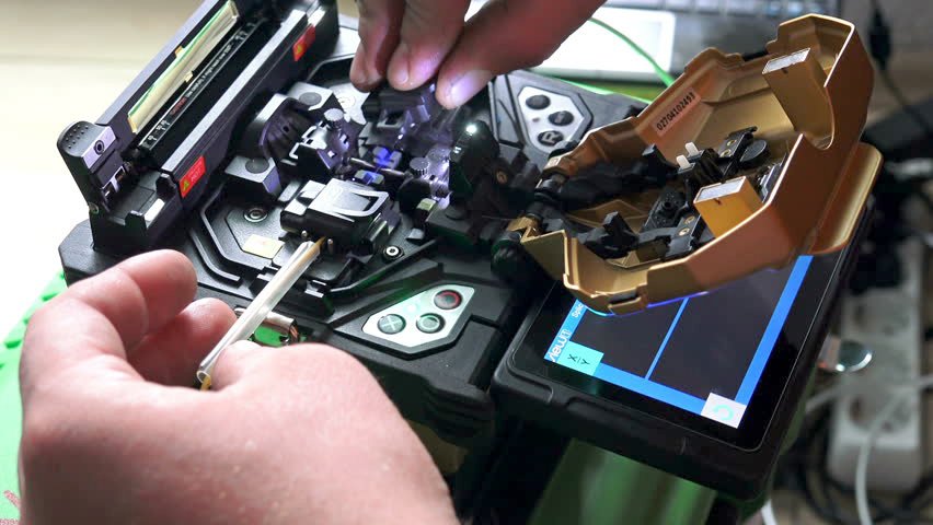
What Does a Fiber Optic Fusion Splicer Actually Do?
The process, while complex internally, is conceptually straightforward. The splicer first uses a set of high-resolution cameras to inspect the prepared fiber ends. It then uses motors with sub-micron precision to align the cores of the two fibers perfectly. Once aligned, the machine generates a controlled electric arc between two electrodes, momentarily melting the glass tips. The molten ends are then pushed together, fusing them into a single, continuous piece of glass. The entire process is automated and typically takes only a few seconds. The splicer then performs an automated test to estimate the loss of the splice, providing the technician with immediate feedback on the quality of the connection.
Core Alignment vs. Cladding Alignment Fusion Splicer Models
Not all fusion splicers are created equal. They primarily fall into two categories based on their alignment method, and choosing the right one depends on the application’s performance requirements.
- Core Alignment Fiber Optic Fusion Splicer: This is the most precise and advanced type. It uses multiple cameras and light sources to look directly at the fiber cores, aligning them independently of the cladding’s outer diameter. This method compensates for any imperfections, such as core eccentricity, ensuring the lowest possible splice loss. Core alignment is the standard for long-haul networks, submarine cables, and other applications where performance is non-negotiable.
- Cladding Alignment Fiber Optic Fusion Splicer: This type of splicer aligns the fibers based on their outer diameter (the cladding). It operates on the assumption that the core is perfectly centered within the cladding. While modern manufacturing has made fibers very consistent, slight variations can still exist. Cladding alignment splicers are faster, more compact, and less expensive, making them a popular choice for shorter-distance networks like FTTH or local area networks (LANs), where slightly higher splice loss is acceptable.
EPCOM offers a range of both core and cladding alignment models, ensuring that technicians have the right tool for the job, whether they are building a national backbone network or connecting a local business.
Mastering the Splicing Process with Your Fiber Optic Fusion Splicer
While a modern fiber optic fusion splicer automates the most critical steps, the final quality of the splice heavily depends on the technician’s preparation. A perfect splice begins long before the fibers enter the machine. Following a meticulous process is key to achieving consistent, low-loss results every single time.
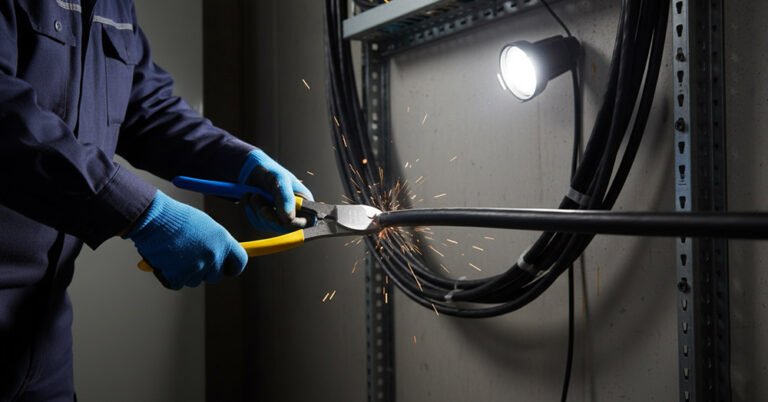
Step 1: Meticulous Preparation and Cable Stripping
The journey to a perfect splice starts with preparing the cable. The technician must carefully strip back the outer jacket, armor, and other protective layers to expose the buffered fibers. Specialized tools are used for this to avoid damaging the delicate glass within. Once the individual fiber is isolated, the buffer coating (typically 250 or 900 micrometers) must be removed using a precise fiber stripper. This exposes the bare cladding, which must be perfectly clean for the next steps.
Step 2: The Critical Importance of Fiber Cleaning
This is arguably one of the most crucial steps. Any dust, oil from skin, or other residue left on the bare fiber can cause catastrophic failure during the fusion process. The contaminant can burn into the glass, creating a massive loss point or a physical weak spot. Therefore, technicians must clean the stripped fiber using lint-free wipes and reagent-grade isopropyl alcohol. Proper cleaning ensures that nothing comes between the two glass ends when they are fused. For reliable and effective cleaning, having the right tools is paramount. EPCOM provides a complete selection of professional optical fiber cleaners designed for field use.
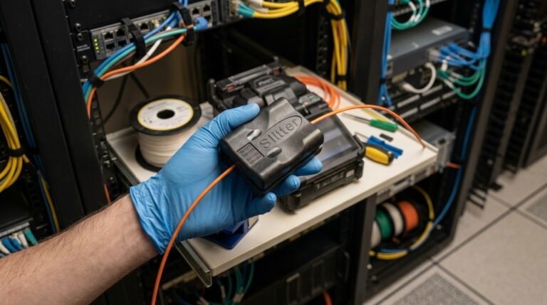
Step 3: recision Cleaving: Key to the Fiber Optic Fusion Splicer’s Success
After cleaning, the fiber must be “cleaved.” This is not cutting but rather a process of scoring the glass and breaking it to produce a perfectly flat end-face that is exactly 90 degrees to the fiber axis. Any angle or imperfection (like a lip, hackle, or chip) on the end-face will prevent a proper fusion and result in high signal loss and back reflection. This step requires a high-precision tool called a fiber cleaver. A quality cleaver is just as important as the splicer itself. Investing in a reliable optical fiber cleaver is non-negotiable for any serious fiber technician.
Step 4: Running the Splicing Program
Once the prepared fibers are loaded into the holders of the fiber optic fusion splicer, the technician closes the lid and initiates the automated splicing sequence. The machine takes over, performing the alignment, fusion, and loss estimation test in a matter of seconds. Modern splicers have pre-configured programs for different types of fiber (e.g., single-mode G.652, multi-mode OM3), and the technician simply selects the appropriate one for the job at hand.
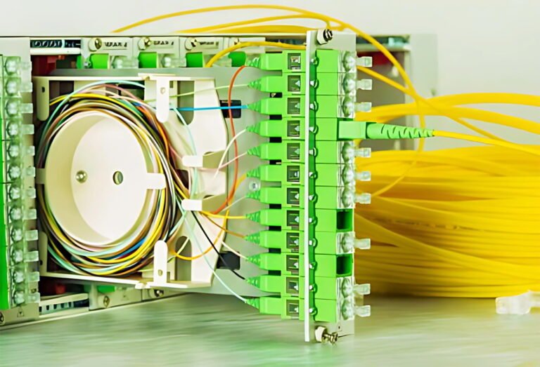
Step 5: Protecting the Splice
A freshly made splice is incredibly fragile. To protect it from bending, moisture, and environmental factors, it must be enclosed in a splice protection sleeve. This is a small tube, typically made of heat-shrinkable plastic with a steel or ceramic strength member inside. Before splicing, the technician slides this sleeve onto one of the fibers. After the splice is complete, they slide the sleeve over the bare splice point and place it in a small oven built into the fusion splicer. The oven heats the sleeve, causing it to shrink tightly around the fiber and providing robust mechanical protection that will last for decades.
Advanced Features in Modern Fiber Optic Fusion Splicer Technology
The technology inside a fiber optic fusion splicer has evolved dramatically over the years. What was once a bulky, lab-grade instrument is now a rugged, portable, and intelligent device designed for the harshest field conditions. Manufacturers, including those whose products are supplied by EPCOM, are constantly innovating to make splicing faster, more reliable, and more user-friendly.
Automation and Artificial Intelligence
Leading-edge splicers now incorporate artificial intelligence (AI) and machine learning algorithms. These systems can analyze the images of the fiber ends in real-time, identify potential issues like dirt or a bad cleave, and alert the technician before a bad splice is made. They also automatically adjust arc power based on environmental conditions like temperature, humidity, and air pressure to ensure a perfect fusion every time. This level of automation reduces human error and increases the first-time success rate, saving valuable time and money on projects.
Ruggedizing the Fiber Optic Fusion Splicer for Field Use
Technicians often work in challenging environments, from dusty construction sites to humid manholes or freezing temperatures on a tower. A modern fiber optic fusion splicer is built to withstand these conditions. Many models feature IP (Ingress Protection) ratings, certifying their resistance to dust and water. They are also designed to be shock-proof and drop-resistant, with rubberized bumpers and robust internal construction that protects the sensitive optics and alignment system from the rigors of daily fieldwork.
Maintaining Your Fiber Optic Fusion Splicer for Peak Performance
A fiber optic fusion splicer is a significant investment, and like any piece of precision equipment, it requires regular maintenance to deliver optimal performance and a long service life. Proper care not only protects the investment but also ensures that every splice made is of the highest quality, preventing costly network failures down the line. Following a simple maintenance routine can make all the difference.
Regular Cleaning of Critical Components
Dust and debris are the enemies of a fusion splicer. It is crucial to regularly clean several key components:
- V-Grooves: These are the tiny channels where the fibers rest for alignment. Any debris in the V-grooves can cause misalignment and result in a bad splice. They should be cleaned frequently with a fine-tipped swab and alcohol.
- Camera Lenses: The objective lenses that view the fibers can also accumulate dust. If the image on the screen appears blurry or has spots, the lenses need gentle cleaning.
- Mirrors: The mirrors that reflect the fiber’s image to the cameras also require periodic cleaning to ensure a clear view for the alignment system.
Electrode Maintenance and Replacement
The electrodes that generate the electric arc wear out over time. With each splice, a tiny amount of the tungsten material is consumed. As they degrade, their performance becomes inconsistent, leading to poor-quality splices. Most splicers keep track of the number of arcs performed. Technicians should replace the electrodes according to the manufacturer’s recommended interval, which is typically every 3,000 to 5,000 arcs. After replacement, an arc calibration test must be performed to stabilize the new electrodes and ensure proper arc power.
Comparison: Core vs. Cladding Alignment Splicer
| Feature | Core Alignment Fiber Optic Fusion Splicer | Cladding Alignment Fiber Optic Fusion Splicer |
|---|---|---|
| Typical Splice Loss | 0.01 – 0.03 dB | 0.03 – 0.07 dB |
| Alignment Method | Direct Core Observation (X, Y, Z axes) | Passive V-Groove (Outer Diameter) |
| Best Application | Long-Haul, Backbone, Data Center, Submarine | FTTH, LAN, Enterprise, shorter links |
| Cost | Higher | Lower |
| Precision | Highest | High (dependent on fiber geometry) |
Beyond the Splice: Testing and Certifying Network Links
Making a good splice is only half the battle. After a link is constructed, it must be thoroughly tested to ensure it meets the project’s performance specifications. The estimated loss provided by the fiber optic fusion splicer is a good initial check, but it doesn’t tell the whole story. Comprehensive testing requires specialized instruments to certify the quality of the entire fiber link, including all splices and connectors.
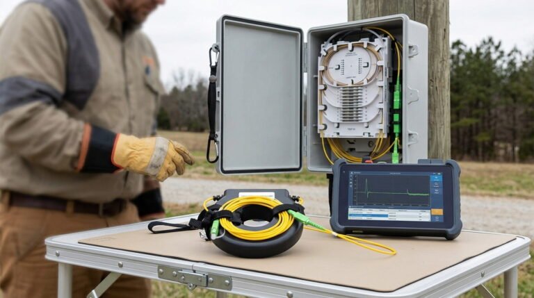
The Indispensable Role of the OTDR
An Optical Time-Domain Reflectometer (OTDR) is the most important tool for characterizing a fiber optic link. It works like radar for fiber optics, sending a high-powered pulse of light down the fiber and measuring the light that is reflected or scattered back. By analyzing the timing and strength of this return signal, the OTDR can create a graphical trace that maps out the entire link. It can pinpoint the location and measure the loss of every splice, connector, and other event along the fiber’s length. This allows technicians to verify that each splice is within tolerance and to easily find and fix any faults. A complete toolkit for any fiber professional must include a high-quality optical fiber tester like an OTDR.
Understanding Splice Loss and Acceptance Criteria
Every network installation has a “loss budget,” which is the maximum amount of signal attenuation that the link can tolerate while still functioning correctly. Industry standards provide guidelines for acceptable loss for different components. For example, according to standards from organizations like the Telecommunications Industry Association (TIA), a fusion splice should typically have a loss of less than 0.1 dB. An OTDR is used to verify that each event on the link meets these criteria. If a splice shows higher loss, it must be remade.
Sources of Signal Loss in a Fiber Optic Link
How to Select the Perfect Fiber Optic Fusion Splicer for Your Needs
Choosing the right fiber optic fusion splicer is a critical decision that depends on a variety of factors. The ideal machine for a team installing a rural FTTH network may be different from the one used in a hyper-scale data center. By carefully considering your specific requirements, you can select a splicer that offers the best balance of performance, durability, and value.
Key Factors for Choosing Your Fiber Optic Fusion Splicer
- Application and Network Type: As discussed, the primary deciding factor is whether you need the ultra-high precision of a core alignment splicer for backbone networks or if the speed and cost-effectiveness of a cladding alignment model are better suited for your local access network projects.
- Fiber Types: Ensure the splicer you choose is compatible with all the types of fiber you work with, whether it’s standard G.652 single-mode, bend-insensitive G.657, or various types of multi-mode fiber.
- Work Environment: If your team works primarily outdoors in varied conditions, prioritize models with high IP ratings for dust and water resistance and a rugged, shock-proof design.
- Budget: While it’s tempting to opt for the least expensive model, it’s important to consider the total cost of ownership. A more reliable splicer that produces fewer failed splices can save significant time and money in the long run.
EPCOM: Your Trusted Partner for the Fiber Optic Fusion Splicer
At EPCOM, we understand the complexities of building and maintaining fiber optic networks. We have curated a selection of the industry’s best tools and equipment to empower technicians to do their job efficiently and effectively. Our range of splicers and accessories is backed by expert support and a commitment to quality. We provide solutions that not only meet the technical demands of today’s networks but also offer the reliability and durability needed for years of field service. When you choose EPCOM, you are not just buying a tool; you are investing in a partnership dedicated to your success. We invite you to explore our extensive catalog of telecom tools and fusion splicers.
Conclusion: The Unseen Heart of Modern Communication
The fiber optic fusion splicer may not be a household name, but it is one of the most critical pieces of technology in our connected society. Every email we send, every video we stream, and every cloud application we use depends on a vast network of optical fibers joined by millions of these precise, almost invisible splices. The skill of the technician, combined with the precision of their tools, is what makes seamless global communication a reality. By understanding the principles of fusion splicing, adhering to best practices in preparation and testing, and investing in high-quality equipment from a trusted supplier like EPCOM, network operators can build robust, reliable, and future-proof infrastructures that will serve the world for generations to come.