Bow Stay Rod Assembly: High-Strength Utility Support
Bow Stay Rod Assembly components play a critical role in stabilizing utility poles across modern electrical distribution networks. Consequently, line designers must prioritize the mechanical structural integrity of overhead lines. To balance horizontal mechanical loads, electrical utilities rely on robust pole line hardware systems. Specifically, when overhead line conductors span vast distances, they exert massive physical forces on wooden, concrete, or steel poles. Therefore, a secure, heavy-duty anchoring foundation is required to prevent structures from tilting or failing entirely. In this regard, the physical stability of distribution grids remains highly dependent on premium-grade, hot-dip galvanized utility metal components that withstand adverse weather conditions.
Historically, environmental factors such as severe windstorms, heavy snowfall, and shifting soils have repeatedly threatened critical electrical infrastructures. To counter these natural forces, engineers must design reliable lateral support structures. Consequently, the combination of high-tensile stay wires, a specialized Bow Stay Rod Assembly, and buried plates forms a highly resilient structural matrix. In particular, this matrix redirects lateral mechanical stress from the upper pole body down to the solid, compacted earth. Furthermore, EPCOM continues to engineer high-performance power distribution solutions to meet strict global safety standards. Through precise metallurgy and manufacturing processes, modern grid components achieve decades of service life with minimal maintenance overhead.
Additionally, material selection is paramount in securing high-voltage power networks. Specifically, structural steel must possess superior yield strength to resist continuous tensile loads without experiencing permanent elongation. In contrast, choosing a substandard Bow Stay Rod Assembly might lead to stress fractures under extreme thermal or physical fluctuations. Therefore, choosing fully compliant hardware components prevents catastrophic cascading failures across major distribution lines. Moreover, utilizing robust accessories optimizes load distribution at every connection joint. Consequently, purchasing from a reputable, certified industrial manufacturer ensures long-term grid safety and overall operational reliability.
What is a Bow Stay Rod Assembly in Utility Grids?
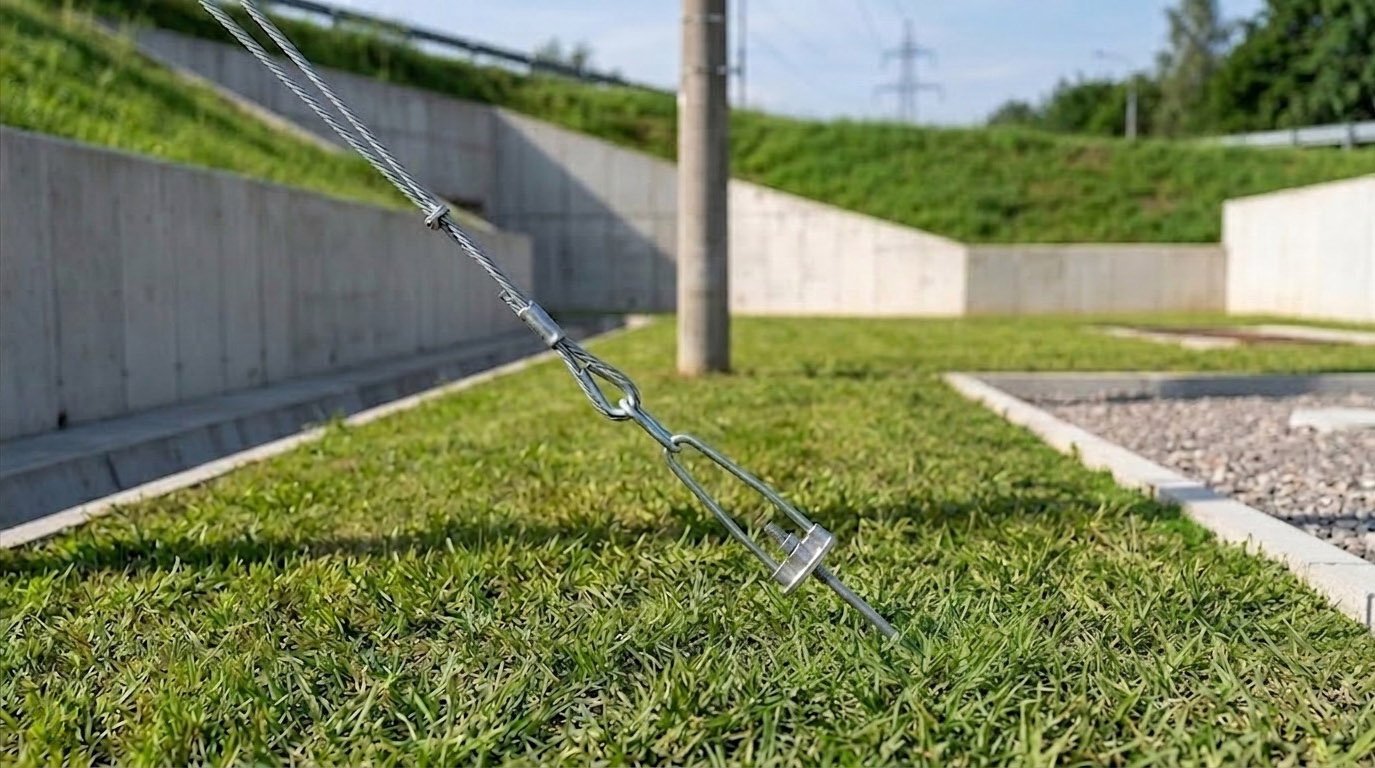
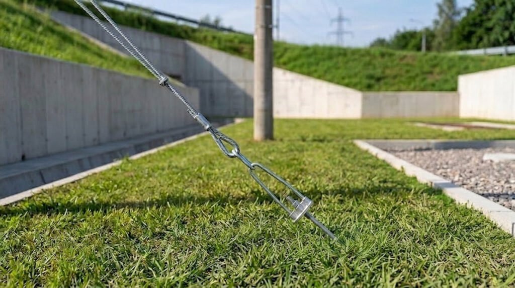
A Bow Stay Rod Assembly is a specialized, heavy-duty mechanical system engineered to anchor utility poles securely to the ground. Specifically, this system consists of several integrated metal components, including a high-tensile anchor rod, a bow-shaped tightener, an adjustable stay thimble, heavy-duty hex nuts, and matching flat washers. In addition, the bow tightener serves as a central adjustment node. This component allows lineworkers to apply precise tension directly to the connected stay wire during initial line construction. Consequently, this precise tensioning creates a perfect counter-balance against the heavy lateral strain exerted by overhead line conductors.
To clarify, the physics behind utility line engineering requires an exact equilibrium of vector forces. For instance, when high-voltage conductors change direction or terminate at dead-end poles, they generate a strong horizontal pull. Without a corresponding counter-force, the utility pole would eventually tilt, causing lines to sag and potentially short-circuit. To prevent this, the robust Bow Stay Rod Assembly is driven into the ground at a calculated angle, typically between 45 and 60 degrees. Subsequently, this stay system acts as a rigid anchor, channeling the lateral force vectors downward into the deep subsoil strata. Consequently, the utility pole remains perfectly vertical, preserving safe clearances between energized conductors and the terrain below.
Furthermore, the physical bow component within the Bow Stay Rod Assembly provides a crucial mechanical advantage. Specifically, it protects the stay wire from sharp bends that could weaken its individual steel strands. Instead, the stay thimble guides the high-tensile wire through a smooth, curved path, distributing the mechanical tension evenly. To guarantee durability, EPCOM fabricates every Bow Stay Rod Assembly from solid, forged steel. In this regard, every single component undergoes a rigorous manufacturing process to eliminate internal structural voids. As a result, the finished hardware system delivers unparalleled performance, even when subjected to continuous cyclic load stresses over several decades of operation.
Additionally, field engineers must understand how the Bow Stay Rod Assembly interacts with various pole structures. For example, wooden poles exhibit greater natural flexibility than concrete structures. Consequently, a flexible pole requires a more forgiving tensioning profile to avoid over-stressing the fibers. In contrast, rigid concrete poles demand immediate and unyielding counter-tension from the Bow Stay Rod Assembly to prevent localized concrete spalling. Therefore, adjusting the tension requires high precision and specialized torque instrumentation during the initial tensioning phase. Ultimately, matching the tension profile to the pole material ensures structural harmony across the grid.
Structural Materials of the Pole Line System
The choice of materials determines the overall longevity and safety of pole line infrastructure. Specifically, utility hardware must endure continuous exposure to outdoor environments, including scorching UV radiation, torrential rain, and industrial chemical emissions. Therefore, high-grade structural carbon steel is selected as the primary raw material for every heavy-duty Bow Stay Rod Assembly. Indeed, carbon steel provides the optimal balance of mechanical ductility, high yield strength, and sheer tensile capacity. Because of these excellent metallurgical properties, the hardware can absorb sudden mechanical impacts, such as falling tree branches, without fracturing.
To prevent rapid oxidation and rust formation, all steel components of the Bow Stay Rod Assembly must undergo the professional process of hot-dip galvanization. Specifically, the steel is thoroughly cleaned in an acid bath before being completely submerged in a molten zinc kettle at temperatures around 450 degrees Celsius. Consequently, this chemical reaction creates a multi-layered zinc-iron alloy coating that is metallurgically bonded to the underlying steel. According to established ANSI standards, this protective zinc barrier must meet precise thickness requirements to ensure decadal protection. Ultimately, this robust galvanized finish prevents moisture and oxygen from reaching the core steel, eliminating the threat of premature structural degradation.
Additionally, different environmental classifications require specific material grades to achieve maximum performance. For example, in coastal regions with highly corrosive saltwater mist, standard coatings might degrade more quickly. In contrast, an advanced Bow Stay Rod Assembly with extra-thick zinc coatings provides superior resistance to marine corrosion. Therefore, evaluating localized climate conditions during the initial system design phase is highly critical. Furthermore, keeping manufacturing processes aligned with international quality benchmarks guarantees that the metal hardware remains physically stable. Consequently, utilizing premium materials protects the massive capital investments made by modern electrical utility companies.
The Mechanical Role of a Stay Plate
At the very bottom of the anchoring system lies the buried foundation element, which must resist enormous upward pulling forces. Specifically, the anchor rod of the Bow Stay Rod Assembly connects directly to a heavy-duty, hot-dip galvanized Stay Plate that is positioned deep within a compacted earthen pit. This flat, wide plate acts as a highly effective physical anchor, distributing the concentrated upward mechanical tension across a vast volume of compacted subsoil. Consequently, the passive weight of the overhead soil overburden, combined with the internal shear strength of the earth, prevents the rod from being pulled straight out of the ground.
Furthermore, the physical dimensions and overall thickness of the plate are precisely calculated based on localized soil density parameters. For instance, in soft, sandy, or muddy soils, a much larger plate area is required to prevent shifting under continuous load. In contrast, in hard, well-compacted clay terrains, a smaller, thicker plate might suffice to achieve the necessary hold for the Bow Stay Rod Assembly. Therefore, proper geological assessment is a vital prerequisite before selecting and installing the anchoring hardware. By pairing a high-tensile anchor rod with a matching, robust plate from EPCOM, engineers can guarantee that the foundation remains structurally immovable for many years.
Additionally, the physical connection between the Bow Stay Rod Assembly and the plate is secured using high-strength forged washers and double-locked hex nuts. This secure locking mechanism prevents the rod from sliding through or detaching from the plate during heavy windstorms or seismic events. To clarify, if this connection were to loosen even slightly, the entire stay system would lose its tension, leading to immediate pole instability. Therefore, utilizing precision-machined threads and heavy-duty structural washers is essential. Ultimately, this deep underground assembly serves as the foundation for the structural integrity of the entire overhead electrical distribution network.
Benefits of Using a Porcelain Suspension Insulator
While mechanical strength is vital for pole line hardware, electrical isolation is equally critical to prevent dangerous electrical faults. Specifically, high-voltage stay wires run from the upper section of the utility pole directly to the ground level, creating a potential pathway for stray electrical currents. To eliminate this severe safety hazard, engineers must integrate a high-grade Porcelain Suspension Insulator into the upper portion of the stay line. This dense, glazed ceramic component effectively interrupts the continuous metal path above the Bow Stay Rod Assembly, preventing leakage currents from traveling down to the ground.
Furthermore, porcelain material exhibits exceptional dielectric strength, meaning it can withstand incredibly high electrical voltages without experiencing electrical breakdown. This property is particularly crucial during severe weather conditions, such as heavy rainstorms, lightning strikes, or dense fog, which naturally increase the risk of surface flashovers. In addition, the smooth, glazed exterior surface of the porcelain insulator is designed to shed water rapidly and resist the accumulation of airborne dust or salt contaminants. Consequently, this self-cleaning design maintains high electrical resistance, even in highly polluted industrial areas or coastal marine environments near the Bow Stay Rod Assembly installation.
Additionally, these ceramic insulators must possess high mechanical tensile strength, as they are placed directly in line with the high-tension stay wire. Specifically, they must transmit thousands of kilograms of continuous mechanical pull down to the Bow Stay Rod Assembly without cracking or shattering under the stress. Therefore, high-quality porcelain is formulated using premium raw clays and fired at precise temperatures to achieve a dense, flawless crystalline structure. By utilizing these advanced insulators, utilities can protect maintenance personnel and the public from accidental electrical shocks. Ultimately, this integration represents a perfect union of mechanical safety and robust electrical engineering.
Key Technical Parameters of Bow Stay Rod Assembly Models
To satisfy diverse utility engineering specifications, these anchoring assemblies are manufactured in various standardized sizes and mechanical capacities. Specifically, the rod diameter within the Bow Stay Rod Assembly directly dictates the ultimate tensile strength of the entire system. For instance, smaller distribution lines might utilize a 16mm diameter rod, while heavy-duty transmission structures require 20mm or 24mm options. In addition, the overall length of the rod is configured to match the calculated depth of the frost line and the local soil density. Consequently, engineers can choose the exact model that matches their structural load requirements.
Furthermore, the thread length on the anchor rod must be sufficient to allow for ample tension adjustment over time. Specifically, as the ground settles or the steel stay wire experiences minor natural stretching, lineworkers must adjust the tension of the Bow Stay Rod Assembly. To facilitate this, the bow tightener must feature precise, clean-cut threads that resist stripping under heavy torque. In this regard, EPCOM ensures that all threads are chased and inspected after the hot-dip galvanization process. This attention to detail guarantees smooth, trouble-free operation during field installation, preventing costly delays for utility crews.
| Model Code | Rod Diameter (mm) | Assembly Length (mm) | Minimum Tensile Strength (kN) | Zinc Coating Weight (g/m²) |
|---|---|---|---|---|
| EP-SRA-16 | 16 | 1800 | 70 | > 460 |
| EP-SRA-18 | 18 | 2000 | 90 | > 500 |
| EP-SRA-20 | 20 | 2440 | 120 | > 550 |
| EP-SRA-24 | 24 | 2700 | 170 | > 610 |
Moreover, modern electrical utility companies require clear engineering visualizations to plan their grid assets. Specifically, understanding the relationship between rod diameter and tensile capacity within the Bow Stay Rod Assembly is critical for line optimization. Below is a detailed vector chart illustrating the mechanical performance curve across various standardized configurations. This chart provides a reference for structural engineers during the initial phase of network design, ensuring that safety margins remain fully compliant with regional regulations.
Tensile Strength Capacity vs. Rod Diameter Curve
Figure 1: Graphical visualization of structural tensile performance curves for high-yield anchoring rods.
Step-by-Step Installation of Bow Stay Rod Assembly Units
The overall reliability of a stay system is heavily dependent on proper field installation techniques. Specifically, even the highest quality metal hardware will fail if it is improperly anchored or aligned. Therefore, utility installation crews must strictly follow standardized civil and electrical construction protocols. Initially, the crew must mark the exact location for the anchor pit, which is typically calculated based on a 45-degree angle from the top of the utility pole. Subsequently, they excavate a narrow, slanted trench that matches this precise angle perfectly. This careful slope planning ensures that the Bow Stay Rod Assembly remains perfectly aligned with the future tensile force vector, preventing lateral shifting after installation.
Furthermore, once the trench is ready, the crew places the stay plate at the deepest end of the excavated pit. Specifically, the anchor rod of the Bow Stay Rod Assembly is inserted through the center hole of the plate, and the locking washers and heavy hex nuts are tightened using high-torque wrenches. Consequently, this secure connection creates a rigid, unified underground assembly. Next, the slanted trench is backfilled with earth. However, this backfilling process must be completed in consecutive layers, with each layer being compacted thoroughly using heavy mechanical rammers. By compacting the earth systematically, the crew maximizes the soil’s resistance to upward pulling forces, which ultimately prevents any displacement of the Bow Stay Rod Assembly under heavy loads.
Additionally, after the underground portion is fully completed, the crew attaches the bow tightener to the exposed end of the rod above ground level. Specifically, the high-tensile stay wire is routed through the stay thimble of the Bow Stay Rod Assembly and secured using appropriate wire grips or preformed guy grips. Subsequently, the lineworkers turn the bow tightener’s adjusting nut to apply the initial mechanical tension to the line. During this crucial stage, the crew must monitor the vertical alignment of the utility pole continuously using precision transits or plumb bobs. Once the pole is perfectly vertical and the tension matches the engineering design, the locking nuts on the Bow Stay Rod Assembly are tightened down completely to secure the entire setup.
Ensuring Proper Anchoring Groundwork
The physical characteristics of the surrounding soil play a decisive role in the overall success of the anchoring process. Specifically, different soil classes exhibit highly variable shear strengths and load-bearing capacities. For instance, in dense, rocky ground, the natural resistance of the terrain is exceptionally high. In contrast, in saturated, clay-rich, or sandy areas, the soil can easily deform under continuous mechanical tension. Therefore, installation engineers must perform localized soil density testing to determine if standard plates are suitable or if a customized Bow Stay Rod Assembly installation is required.
To clarify, when dealing with extremely soft or unstable ground, standard soil compaction may not provide sufficient anchoring force. In these challenging situations, engineers often opt to pour a wet concrete block around the stay plate within the pit to hold the Bow Stay Rod Assembly. This technique effectively increases the physical mass and total surface area of the anchor, distributing the upward tension across a much larger volume of material. Consequently, this concrete reinforcement prevents the rod from pulling upward, even under hurricane-force winds. Ultimately, understanding these geological variables allows EPCOM to supply the correct configuration of hardware for any installation environment.
Additionally, moisture content is a major factor that influences soil stability and the rate of metal corrosion over time. Specifically, poorly drained soil types retain water for extended periods, creating a highly corrosive environment for underground metal components of the Bow Stay Rod Assembly. Therefore, ensuring that all buried hardware features an exceptionally thick, high-quality zinc coating is absolutely mandatory. Furthermore, implementing proper surface grading around the guy wire exit point prevents surface water from pooling and running directly down the rod. By combining these civil engineering practices with a premium Bow Stay Rod Assembly, utilities can guarantee an exceptionally long, maintenance-free service life.
Connecting Cables with JBT Parallel Groove Connector Hardware
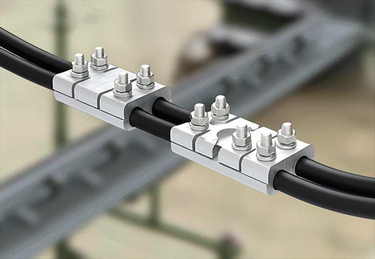
In addition to securing the physical pole, maintaining flawless electrical connectivity across overhead distribution lines is highly critical. Specifically, when utility crews install overhead lines, they must establish secure, high-conductivity electrical connections between adjacent conductors. To achieve this, lineworkers utilize a high-quality JBT Parallel Groove Connector. This specialized aluminum-alloy connector features parallel grooves designed to clamp two bare conductors together with exceptional mechanical force, ensuring continuous current flow without resistance above the Bow Stay Rod Assembly anchoring point.
Furthermore, these connectors are engineered to accommodate a wide range of conductor cross-sectional areas. For instance, in high-voltage distribution networks, aluminum conductors steel-reinforced (ACSR) of varying diameters must be joined safely. To prevent loose connections that could lead to electrical arcing and severe power outages, the connector’s bolts must be tightened to precise torque specifications. In addition, the internal grooves of the connector are often pre-filled with a high-performance electrical joint compound. This specialized compound breaks through the naturally occurring oxide film on the aluminum surfaces, preventing future oxidation and keeping the contact resistance extremely low near the Bow Stay Rod Assembly installation area.
Additionally, material compatibility is a major engineering consideration when selecting electrical connectors. Specifically, joining dissimilar metals, such as aluminum and copper, can lead to severe galvanic corrosion when exposed to moisture. To prevent this, EPCOM manufactures specialized bimetallic connectors that feature copper linings in one groove and aluminum in the other. This advanced design effectively isolates the two metals, preventing chemical degradation and preserving the structural and electrical integrity of the joint. Ultimately, integrating these high-performance connectors into the network alongside a reliable Bow Stay Rod Assembly ensures maximum transmission efficiency and overall operational safety.
Quality Manufacturing Processes at EPCOM
To ensure that every piece of utility hardware can withstand the demanding conditions of long-term outdoor service, production quality must be controlled rigorously. Specifically, EPCOM operates state-of-the-art forging and hot-dip galvanizing lines that utilize advanced manufacturing technologies. During the initial fabrication stage, raw carbon steel bars for the Bow Stay Rod Assembly are carefully inspected for chemical composition and structural uniformity. Subsequently, high-precision automated shearing machines cut the steel to exact lengths, preparing the material for the hot forging process. This automated precision ensures that every single component matches the engineered blueprint with microscopic tolerances.
Furthermore, the hot forging process is monitored continuously using infrared temperature sensors. This real-time thermal monitoring ensures that the steel of the Bow Stay Rod Assembly is forged within the optimal temperature range to prevent internal micro-cracks or structural weaknesses. Once the forging process is complete, the components undergo a series of mechanical tests, including destructive tensile testing and non-destructive ultrasonic evaluations. These rigorous quality checks guarantee that every rod and bow tightener can easily withstand loads far exceeding their rated capacities. Consequently, utilities can install this Bow Stay Rod Assembly hardware with absolute confidence, knowing that it provides a significant safety margin.
Additionally, the hot-dip galvanizing process at EPCOM is executed with meticulous attention to environmental and metallurgical details. Specifically, the steel components are treated in successive cleaning and fluxing baths to remove all trace impurities before entering the molten zinc kettle. This thorough preparation ensures an incredibly uniform zinc layer that adheres permanently to the steel substrate of the Bow Stay Rod Assembly. After galvanizing, each thread is carefully chased and inspected to ensure smooth, effortless threading during field assembly. By maintaining these exceptionally high manufacturing standards, the finished hardware achieves a level of durability that sets the benchmark for the entire power distribution industry.
Critical Maintenance Practices for Bow Stay Rod Assembly Infrastructure
Even the most durable pole line hardware requires systematic inspections and maintenance to ensure continued reliability over decades of service. Specifically, environmental changes, ground settling, and extreme weather events can gradually alter the physical tension of the stay system. Therefore, electrical utility operators must implement routine, scheduled maintenance programs. During these field inspections, maintenance crews utilize specialized diagnostic tools to measure the mechanical tension of individual stay wires connected to the Bow Stay Rod Assembly. Consequently, any significant drop in tension can be detected early and corrected before it leads to structural instability.
Furthermore, visual inspections are essential to detect early signs of physical wear or environmental degradation. Specifically, lineworkers look for any signs of corrosion, such as peeling zinc coatings or reddish-brown rust spots near the ground line of the Bow Stay Rod Assembly. If corrosion is detected, the affected components must be cleaned and treated immediately with zinc-rich cold galvanizing compounds to prevent further deterioration. In addition, the inspection crew must examine the ceramic insulators for any cracks, chips, or severe dirt accumulation. Replacing damaged insulators promptly is critical to maintaining proper electrical isolation and preventing dangerous leakage currents from traveling down to the Bow Stay Rod Assembly.
Additionally, checking the tightness of all exposed nuts and bolts is a key component of the preventative maintenance checklist. Specifically, wind vibrations and thermal expansion can gradually loosen threaded connections of the Bow Stay Rod Assembly over time. Therefore, maintenance technicians must retorque all nuts on the bow tightener and anchor rod using calibrated torque wrenches. Furthermore, inspecting the ground surface around the anchor rod exit point is crucial to ensure that erosion has not exposed the buried stay plate. By implementing these rigorous maintenance practices, utilities can maximize the service life of their anchoring infrastructure. Ultimately, this proactive approach guarantees a highly stable, exceptionally safe, and continuously reliable power transmission network.