

Mastering the Fiber Patch Cord for Peak Networks
A Fiber Patch Cord is the cornerstone of modern, high-speed data transmission, acting as the critical link that connects network devices for seamless communication. In an era dominated by data, from sprawling data centers to fiber-to-the-home (FTTH) installations, understanding the nuances of these essential components is no longer optional—it is fundamental to achieving peak network performance. These cables, also known as fiber optic patch cables or jumpers, are designed to transmit information as pulses of light, offering unparalleled speed, bandwidth, and immunity to electromagnetic interference compared to traditional copper cables. As network demands continue to explode, selecting the correct type of fiber patch cord from a reliable provider like EPCOM is paramount. This comprehensive article delves deep into every facet of fiber patch cords, exploring their construction, diverse types, selection criteria, installation best practices, and advanced applications. Whether you are a network administrator, an IT professional, or a technician in the field, this text will equip you with the knowledge to navigate the complexities of fiber optic connectivity and build robust, future-proof networks.
The Anatomy of a High-Performance Fiber Patch Cord
Core Components of a Fiber Patch Cord
To truly appreciate the function of a fiber patch cord, one must first understand its intricate construction. Each layer is meticulously engineered to protect the fragile glass core and ensure the flawless transmission of light over short or long distances. At its heart is the Core, a microscopic strand of ultra-pure silica glass, which is the actual medium for light travel. The diameter of this core is a defining characteristic, determining whether the cable is single-mode or multi-mode. Surrounding the core is the Cladding, another layer of glass with a lower refractive index. This difference in refractive indices is what enables a phenomenon known as Total Internal Reflection, effectively trapping the light within the core and allowing it to propagate down the cable with minimal loss.
Protecting these delicate optical layers is the Buffer Coating, a plastic layer that provides the first line of defense against physical damage and moisture. This coating is often color-coded for easy identification. The next layer is typically composed of Aramid Yarn (often known by the brand name Kevlar®), a high-strength synthetic fiber that provides tensile strength, protecting the cable from being damaged when pulled. Finally, the entire assembly is encased in an outer Jacket. The jacket is the cable’s primary shield against environmental factors like abrasion, oil, and UV radiation. Its material composition (such as PVC, LSZH, or Plenum) is chosen based on the specific application and safety requirements of the installation environment. At each end of the cable are the connectors, which provide a secure and precise alignment with network devices.
How Fiber Patch Cords Transmit Data with Light
The magic of a fiber patch cord lies in its ability to transmit data at nearly the speed of light. This process begins when an electronic signal from a network device is converted into a light pulse by a transmitter, typically a laser or a Light Emitting Diode (LED). This pulse is precisely aimed into the core of the fiber optic cable. As the light travels down the core, it continuously strikes the boundary between the core and the cladding at a shallow angle. Because the cladding has a lower refractive index, the light does not escape; instead, it is completely reflected back into the core. This process, known as Total Internal Reflection, acts like a perfect mirror, guiding the light pulse along the length of the fiber with incredibly low signal loss, or attenuation.
When the light pulse reaches the other end of the cable, a photodetector in the receiver converts it back into an electronic signal that the receiving network device can understand. The speed and efficiency of this process allow for massive amounts of data to be transmitted over vast distances. Unlike copper cables, which are susceptible to electromagnetic interference (EMI) and signal degradation over distance, fiber optic signals are immune to such noise. This immunity ensures a cleaner, more reliable signal, which is critical for sensitive applications in telecommunications, data centers, medical imaging, and broadcasting. The result is superior bandwidth, enhanced security, and the capacity to handle the ever-increasing data demands of our connected world.
Exploring the Diverse Types of Fiber Patch Cords
Single-Mode vs. Multi-Mode: The Core Difference in a Fiber Patch Cord
One of the most fundamental distinctions in the world of fiber optics is between single-mode and multi-mode fiber patch cords. The choice between them dictates the network’s distance capabilities, bandwidth, and overall cost. The primary difference lies in the diameter of the fiber core.
Single-Mode Fiber (SMF) Patch Cords feature an incredibly small core, typically around 9 micrometers (µm) in diameter. This tiny aperture permits only one mode, or path, of light to travel down the fiber. By forcing the light into a single, straight path, single-mode fiber minimizes modal dispersion—a phenomenon where different light paths arrive at the receiver at slightly different times, which can corrupt the signal at high speeds and long distances. This characteristic allows single-mode fiber to carry signals over enormous distances (many kilometers) with extremely high bandwidth, making it the standard for long-haul telecommunications, CATV networks, and inter-building campus backbones. They typically use a high-powered, more expensive laser light source and are identifiable by a yellow outer jacket.
Multi-Mode Fiber (MMF) Patch Cords, in contrast, have a much larger core, usually 50 µm or 62.5 µm. This larger core allows multiple modes of light to propagate simultaneously, each bouncing along the fiber at a different angle. While this makes the system less expensive to operate—as it can use cheaper light sources like LEDs or VCSELs (Vertical-Cavity Surface-Emitting Lasers)—it also introduces modal dispersion. This dispersion limits the effective reach and bandwidth of multi-mode fiber. Consequently, it is best suited for shorter-distance applications, such as within a single building or a data center. Multi-mode cables are categorized into different grades (OM1, OM2, OM3, OM4, OM5), each offering progressively better performance. They are typically identified by an orange (OM1/OM2), aqua (OM3/OM4), or lime green (OM5) jacket.
Simplex vs. Duplex Fiber Patch Cord Configurations
Beyond the type of fiber, patch cords are also classified by their strand count and communication method, primarily as simplex or duplex.
A Simplex Fiber Patch Cord consists of a single strand of fiber with a single connector at each end. It is used for applications that only require one-way data transmission. In a simplex setup, a signal can travel from device A to device B, but not simultaneously from B to A on the same strand. This configuration is common in applications like digital signage, broadcast video feeds, and certain types of automated control systems where information flows in only one direction.
A Duplex Fiber Patch Cord, on the other hand, consists of two strands of fiber joined together, often in a zip-cord style. This configuration allows for simultaneous, bi-directional communication, a mode known as full-duplex. One strand transmits data from device A to device B, while the second strand transmits from B to A. This is the most common configuration for network equipment like switches, servers, and transceivers, which require a constant two-way flow of information to function. Duplex patch cords have two connectors at each end, often held together by a clip to ensure proper transmit (Tx) and receive (Rx) alignment.
How to Choose the Right Fiber Patch Cord for Your Network
Selecting the appropriate fiber patch cord is a critical decision that directly impacts network reliability, performance, and scalability. With a multitude of options available, making an informed choice requires a careful evaluation of your specific requirements. Key factors include the network environment, the distance of the connection, the required data rate, and the type of equipment being used. By systematically considering each variable, you can ensure that you invest in the right components to build a robust and efficient fiber optic infrastructure with EPCOM.
Key Selection Criteria for a Fiber Patch Cord
To simplify the selection process, consider the following critical factors:
- Connector Type (LC, SC, ST, etc.): The connectors on the patch cord must match the ports on your equipment. The most common types are LC (Lucent Connector) and SC (Subscriber Connector) due to their high performance and compact design. However, legacy systems may still use ST (Straight Tip) or FC (Ferrule Connector) types. Always verify the port type on your switches, transceivers, and patch panels before purchasing.
- Fiber Mode (Single-Mode vs. Multi-Mode): This is the most important decision. For long distances (over 550 meters) and future-proofing for higher bandwidth, single-mode is the clear choice. For shorter distances, such as within a data center or a single building, a high-grade multi-mode (like OM3, OM4, or OM5) is a more cost-effective solution.
- Cable Length and Diameter: Order cables that are slightly longer than your measurement to avoid stress on the connectors, but not so long that they create a tangled mess of slack. Cable diameter can also be a factor in high-density environments, where thinner “slim” or “uniboot” cables can improve airflow and reduce congestion.
- Jacket Material (Riser, Plenum, LSZH): The jacket’s fire rating must comply with local building codes. Plenum-rated (OFNP) cables are required for installation in plenum spaces (like drop ceilings or raised floors) due to their fire-retardant properties and low smoke emission. Riser-rated (OFNR) cables are suitable for vertical runs between floors in non-plenum environments. Low Smoke Zero Halogen (LSZH) jackets are used in enclosed or poorly ventilated spaces where exposure to toxic smoke during a fire is a major concern.
- Polish Type (UPC vs. APC): The connector end-face polish affects the cable’s return loss performance. UPC (Ultra Physical Contact) connectors have a slightly domed end-face and offer good performance for most digital applications. APC (Angled Physical Contact) connectors feature an 8-degree angled end-face, which reflects light back into the cladding rather than the source. This provides superior return loss performance, making APC connectors the standard for RF and analog video signals and other sensitive applications. UPC connectors are typically blue, while APC connectors are green.
| Feature | Single-Mode Fiber (SMF) | Multi-Mode Fiber (MMF) |
|---|---|---|
| Core Diameter | ~9 µm | 50 µm or 62.5 µm |
| Light Source | Laser | LED / VCSEL |
| Max Distance | > 10 km (can be much longer) | Up to ~550m for 10GbE (OM4) |
| Bandwidth | Virtually unlimited | Limited by modal dispersion |
| Typical Application | Long-haul telecom, CATV, campus backbone | Data centers, LAN, within buildings |
| Cost | Higher initial electronics cost | Lower electronics cost |
| Jacket Color | Yellow | Orange (OM1/2), Aqua (OM3/4), Lime (OM5) |
Fiber Patch Cord Installation and Maintenance
Proper installation and diligent maintenance are crucial for ensuring the long-term performance and reliability of any fiber optic network. While fiber patch cords are robustly designed, the glass fibers within are delicate and susceptible to damage from improper handling. Furthermore, contamination on the connector end-faces is the number one cause of network failure. Adhering to best practices for handling, installation, and cleaning will prevent common issues, minimize downtime, and protect your investment in high-quality network infrastructure from EPCOM.
Proper Handling and Installation of a Fiber Patch Cord
The golden rule of fiber installation is to treat the cables with care. One of the most critical factors to monitor is the bend radius. Every cable has a minimum bend radius specified by the manufacturer. Bending a cable tighter than this limit can cause micro-cracks in the fiber, leading to signal attenuation or complete failure. A good rule of thumb is to never bend a cable to a radius less than 10 times its outer diameter. When routing cables, avoid sharp corners, and use conduits or cable trays with sweeping bends.
Additionally, never pull a fiber patch cord by the cable itself; always pull from the connector boot, which is designed to handle the stress. Excessive pulling force can stretch the fiber or damage the connector’s internal components. During installation, use dust caps to protect the connector end-faces from contamination and scratches until the moment you are ready to plug them in. Finally, ensure proper slack management. Leaving a small service loop of extra cable can make future moves, adds, and changes much easier, but avoid leaving excessively long loops that can become a tangled mess and a source of potential damage.
The Critical Importance of Cleaning Tools and Procedures
A single speck of dust, an oil fingerprint, or a film of moisture on a connector end-face can have a devastating impact on network performance. Contamination can block the light signal, causing high insertion loss and return loss, or even permanently damage the connector by creating pits and scratches when mated. For this reason, the mantra of every fiber technician is “inspect, clean, and inspect again.” Before ever making a connection, you should inspect the end-face with a specialized fiber scope. If any contamination is visible, it must be cleaned.
For efficient and reliable cleaning, professional tools are indispensable. One of the most effective tools for field technicians is the Fiber Optic Cassette Cleaner. This device provides a simple, one-push operation that advances a fresh section of lint-free cleaning fabric, ensuring a clean surface every time. It is far superior to using canned air (which can propel contaminants) or traditional wipes and solvents (which can leave residue if used improperly). Investing in a high-quality tool like the cassette cleaner from EPCOM is a small price to pay for ensuring the integrity of multi-million dollar network infrastructure. Consistent cleaning protocols are the backbone of a healthy fiber optic network.
Connecting and Securing Your Network Infrastructure
Once your fiber patch cords are clean, the final step is to make the physical connections. This involves more than just plugging in the cable; it requires the use of appropriate hardware to ensure stable, secure, and organized connections. This is where components like adapters and faceplates play a vital role. Fiber optic adapters, also known as couplers, are small devices used to link two fiber optic cables together. They are essential for extending cable runs or for connecting patch cords to the main network backbone at a patch panel. For instance, a high-quality ST Fiber Optic Adaptor is specifically designed to align two ST-terminated cables with extreme precision, ensuring minimal signal loss at the connection point. Using well-machined adapters from EPCOM is critical for maintaining a strong and stable link.
For terminating fiber connections at a user workstation or in a communications closet, a faceplate provides a clean and professional interface. A component like the 4 Cores Fibre Optic Faceplate offers a secure and organized termination point for up to four fiber strands. It protects the delicate termination points from physical damage and provides clearly labeled ports for easy connection of patch cords. By using faceplates, you create a structured cabling system that is not only aesthetically pleasing but also far easier to manage, troubleshoot, and scale in the future. These components are the unsung heroes of a well-organized network, providing the essential framework for reliable connectivity.
Advanced Applications of the Modern Fiber Patch Cord
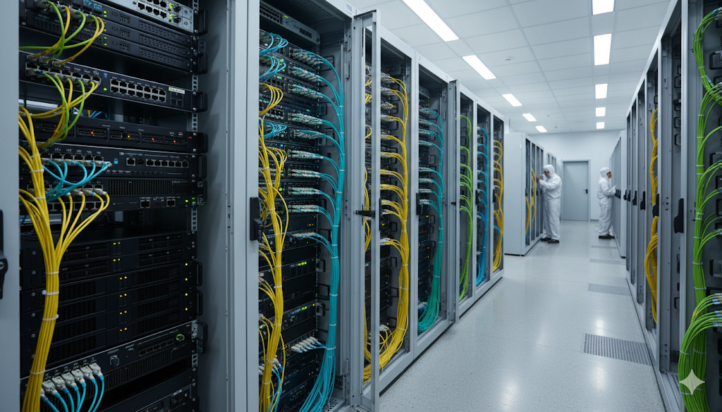
Fiber Patch Cord Applications in High-Density Data Centers
Modern data centers are the heart of the digital economy, and they rely on an incredibly dense and complex web of fiber optic connections. In this environment, every square inch of rack space is valuable, and airflow is critical for cooling. This has driven the adoption of high-density fiber patch cords and connectors. Multi-fiber Push-On (MPO/MTP) connectors, which can terminate 12, 24, or more fibers in a single connector, have become the standard for high-speed trunking between switches. These trunks connect to cassettes or breakout modules, which then distribute the connections to individual servers via standard LC or SC patch cords. Uniboot patch cords, which use a single round cable and a special connector to carry two fibers, are also popular as they can cut the amount of cabling in half, dramatically improving cable management and airflow in packed server racks. The performance of these specialized fiber patch cords is absolutely critical for supporting the 40G, 100G, and even 400G data rates that power cloud computing, big data, and artificial intelligence.
Bandwidth Comparison of Fiber Types (10 Gigabit Ethernet)
The Future of Connectivity and the Role of EPCOM
The demand for faster, more reliable data transmission is relentless. The rollout of 5G networks, the proliferation of Internet of Things (IoT) devices, the rise of autonomous vehicles, and the development of smart cities all depend on a powerful and pervasive fiber optic backbone. As technology evolves, so too will the fiber patch cord. We are already seeing advancements in bend-insensitive fiber, which is more forgiving of tight bends, and new connector types that offer even higher density and lower loss. The principles of quality, reliability, and precision will remain constant.
At EPCOM, we are committed to being at the forefront of this evolution. We understand that a network is only as strong as its weakest link, which is why we provide a comprehensive portfolio of high-quality fiber patch cords, connectors, adapters, and cleaning tools that meet and exceed industry standards. Our products are rigorously tested to ensure they deliver the performance and reliability your critical applications demand. For more information on fiber optic standards, the Fiber Optic Association (FOA) is an excellent resource for industry professionals.
Conclusion: Your Partner in High-Performance Networking
The humble fiber patch cord is a marvel of modern engineering, enabling the global flow of information that underpins our digital lives. From its core construction to the vast array of types and applications, making the right choice is essential for building a network that is not just functional, but exceptional. By understanding the key differences between single-mode and multi-mode, the importance of connector types and polish, and the critical need for proper installation and maintenance, you are empowered to design and deploy a network with confidence.
Whether you are building a state-of-the-art data center, expanding a campus network, or deploying a fiber-to-the-home solution, EPCOM is your trusted partner. We provide the high-quality components and expert support you need to build a fast, reliable, and future-proof network. Contact us today to discuss your project and discover how our fiber optic solutions can help you achieve your connectivity goals.