

The Essential Role of Fiber Optic Loopback Testing
A Fiber Optic Loopback is an indispensable tool in the world of high-speed data transmission, providing a simple yet highly effective method for testing the functionality and performance of fiber optic network equipment. In an era where network uptime and reliability are paramount, having a robust testing methodology is not just an advantage; it’s a necessity. These compact devices are engineered to provide a return signal path for optical signals, allowing network technicians and engineers to perform critical diagnostic tests, isolate faults, and ensure that network components are operating at their peak potential. Whether in a manufacturing facility, a sprawling data center, or out in the field, the fiber optic loopback serves as a cornerstone of efficient network maintenance and troubleshooting, saving both time and resources by quickly identifying issues at the physical layer.
Understanding the Core of Fiber Optic Loopback
To truly appreciate the value of a Fiber Optic Loopback, it is essential to understand its fundamental principles and the mechanisms that make it such a powerful diagnostic tool. At its core, a loopback is designed to simulate a complete optical link in a controlled, localized manner. This simulation allows for the individual testing of network devices without the complexity and variables of a full-scale, end-to-end network connection. By creating a closed loop, technicians can verify the operational integrity of transmitters and receivers, which are the foundational components of any optical communication system. This foundational testing capability is what makes the fiber optic loopback a go-to device for any serious network professional.
What is a Fiber Optic Loopback in Detail?
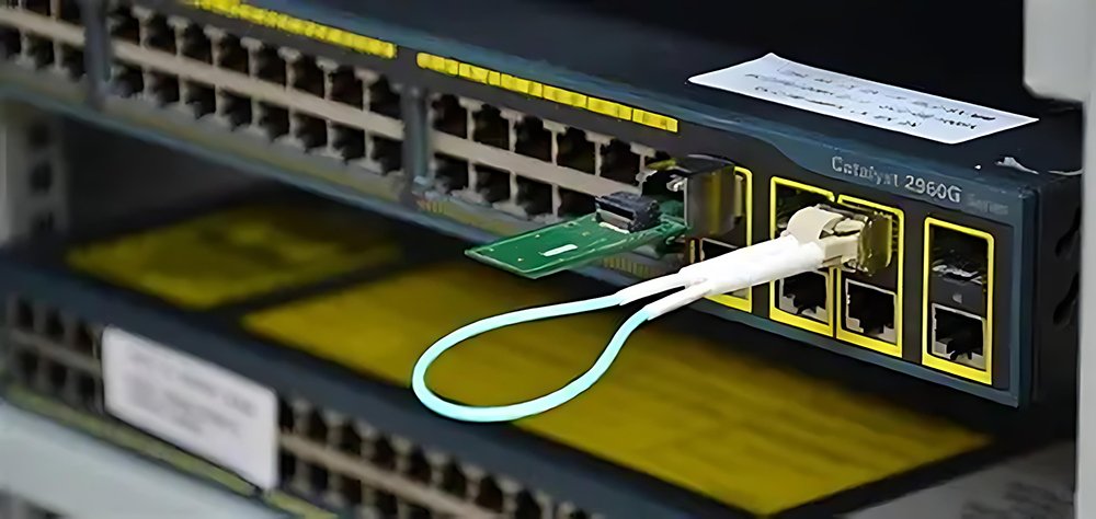
A Fiber Optic Loopback, often referred to as a loopback adapter or loopback plug, is a passive hardware device that connects the transmit (Tx) port of an optical transceiver directly to its receive (Rx) port. This physical connection creates a looped signal path. When the transceiver emits a light signal, it travels out of the Tx port, through the loopback’s fiber optic cable, and immediately enters the Rx port of the same device. This process effectively makes the device “talk to itself.” The primary purpose of this action is to test the functionality of the transceiver. If the device successfully sends and receives its own signal without errors, it confirms that the transceiver itself is functioning correctly. This simple test is the first and most crucial step in diagnosing a wide range of network connectivity problems, as it definitively rules out the device being tested as the source of the fault.
How a Fiber Optic Loopback Module Works
The operational mechanism of a Fiber Optic Loopback is elegantly simple yet precise. The device consists of a short length of optical fiber cable that has been terminated at both ends with connectors that match the ports of the device being tested (e.g., LC, SC, MPO/MTP). The fiber optic strand is protected by a ruggedized housing that not only protects the delicate fiber but also makes it easy to handle and plug into network equipment. When the loopback is plugged into a transceiver port, the light signal generated by the transceiver’s laser diode travels through the fiber, is guided by the loop, and is directed back into the photodiode of the receiver port on the very same transceiver. The device’s internal electronics then check if the received signal matches the transmitted signal in terms of power, wavelength, and data integrity. A successful loopback test, often indicated by a solid link light on the switch or network card, provides immediate confirmation that the port’s transmit and receive functions are operational.
The Critical Role of a Fiber Optic Loopback in Troubleshooting
In network troubleshooting, the process of elimination is key. The Fiber Optic Loopback is the ultimate tool for this process. When a network link goes down, the potential causes are numerous: a faulty transceiver at either end, a break or damage in the long-haul fiber cable, a dirty connector, or a misconfiguration in the software. By using a loopback, a technician can immediately isolate the problem. For instance, if a loopback test is performed on a switch port and it passes, the technician instantly knows that the switch’s transceiver is not the problem. This allows them to focus their attention on the cabling infrastructure or the device at the far end of the link. Without a loopback, a technician might waste hours replacing functional components or painstakingly inspecting miles of cable. Therefore, the fiber optic loopback streamlines the troubleshooting workflow, significantly reduces network downtime, and ultimately lowers operational costs.
Exploring Different Types of Fiber Optic Loopbacks
The market offers a diverse range of Fiber Optic Loopback devices, each designed to meet specific testing requirements related to different fiber types, connector interfaces, and application environments. Understanding these variations is crucial for selecting the right tool for the job. The choice of a loopback depends entirely on the network architecture and the equipment being tested. Using the wrong type of loopback can lead to inaccurate test results or even damage to the equipment. EPCOM provides a comprehensive portfolio of loopbacks to ensure that network professionals have access to the precise tools they need for any scenario, from single-fiber testing to complex, high-density MPO environments.
Singlemode vs. Multimode Fiber Optic Loopbacks
The most fundamental distinction between Fiber Optic Loopback types is based on the type of optical fiber they use: singlemode or multimode.
- Singlemode Fiber Optic Loopbacks (OS1, OS2): These are designed for testing equipment that uses singlemode fiber, which has a small core (typically 9 µm) and is used for long-distance transmissions. They are typically paired with laser light sources and are essential for testing components in telecommunications networks, cable television infrastructure, and long-haul data center interconnects.
- Multimode Fiber Optic Loopbacks (OM1, OM2, OM3, OM4, OM5): These are built with multimode fiber, which has a larger core (50 µm or 62.5 µm) and is used for shorter-distance applications, such as within a building or a data center. They are used to test equipment that employs LED or VCSEL light sources. With the rise of high-speed, short-reach data center applications, OM3, OM4, and OM5 loopbacks have become particularly important for verifying the performance of 40G, 100G, and even 400G transceivers.
Common Connector Interfaces for Fiber Optic Loopbacks
A Fiber Optic Loopback must have connectors that physically match the port of the device under test. Over the years, several connector standards have emerged, and loopbacks are available for all of them. Some of the most common types include:
- LC (Lucent Connector) Loopbacks: These are very popular due to their small form factor and are widely used in high-density applications.
- SC (Subscriber Connector) Loopbacks: Known for their push-pull design, SC connectors are durable and commonly used in a variety of networking applications.
- MPO/MTP Loopbacks: The MPO (Multi-fiber Push-On) connector is a high-density interface that can accommodate multiple fibers (from 8 to 72) in a single connector. MTP® is a high-performance brand of MPO connector. These loopbacks are absolutely essential for testing parallel optics transceivers used in 40G, 100G, and higher-speed Ethernet. They are designed to loop back multiple fiber channels simultaneously, making them vital for data center operations.
Step-by-Step Guide to Fiber Optic Loopback Testing
While the concept of a Fiber Optic Loopback test is straightforward, following a systematic process is key to achieving reliable and meaningful results. A disciplined approach ensures that the test is conducted safely and that the results are interpreted correctly, leading to an efficient resolution of the network issue. This process involves more than just plugging in the device; it includes proper preparation, careful execution, and thoughtful analysis. Rushing through the steps or neglecting preliminary checks can lead to false negatives or positives, sending the troubleshooting process in the wrong direction and wasting valuable time.
Preparing for a Fiber Optic Loopback Test
Proper preparation is the foundation of a successful diagnostic test. Before even touching a Fiber Optic Loopback, a few critical steps must be taken. First, ensure you have the correct type of loopback for the transceiver you are testing—match the fiber type (singlemode/multimode) and the connector type (LC, SC, MPO, etc.). Second, and most importantly, is the cleanliness of the connectors. The core of a fiber optic cable is microscopic, and even a tiny speck of dust or oil can obstruct the light signal, leading to high loss and a failed test. This is why a tool like the Fiber Optic Cassette Cleaner from EPCOM is not just recommended, but essential. Always clean both the transceiver’s port and the loopback’s connectors before every test. This simple act can prevent countless hours of confusion and is a hallmark of a professional technician.
Executing the Fiber Optic Loopback Test: A Walkthrough
With the preparation complete, executing the Fiber Optic Loopback test is a quick process.
- Disconnect the Network Cable: Carefully unplug the live network fiber optic cable from the transceiver port you intend to test. Be sure to place the protective dust cap back on the network cable connector to keep it clean.
- Insert the Loopback: Take the cleaned fiber optic loopback and firmly plug it into the transceiver port. You should feel or hear a click, indicating it is securely seated.
- Observe the Link Status Indicator: Most network devices have an LED indicator light for each port. Once the loopback is connected, this light should turn on (usually solid green), indicating that a link has been established. This is your first positive sign. If the light does not turn on or is blinking amber, it suggests an immediate problem with the port.
- Check the Device’s Management Interface: For a more detailed confirmation, log into the switch’s or server’s software interface. The port status should show as “Up” or “Connected.” The interface may also provide information about the data packets being sent and received, which should be increasing without any errors.
Analyzing Results from Your Fiber Optic Loopback Test
Interpreting the results of a Fiber Optic Loopback test is generally straightforward.
- Successful Test (Link Light On, Port Status “Up”): This result indicates that the transceiver’s transmitter and receiver are functioning correctly. The problem is very likely located elsewhere in the network path, such as in the main fiber optic cabling, the patch panel, or the device at the opposite end of the link. You can confidently move your troubleshooting efforts further down the line.
- Failed Test (No Link Light, Port Status “Down”): This result points to a problem with the local device. The issue could be a faulty transceiver, a misconfigured port, or a problem with the device’s hardware itself. The next logical step is to try a different, known-good transceiver in the same port. If that also fails, the problem lies with the port on the switch or card. If the new transceiver works, then the original transceiver was faulty and should be replaced.
Prime Applications for Loopback Technology
The utility of Fiber Optic Loopback technology extends far beyond simple troubleshooting. These devices are used in a variety of contexts throughout the entire lifecycle of network equipment, from the manufacturing floor to live data center environments. Their versatility makes them a staple in the toolkit of anyone involved in the design, production, installation, or maintenance of fiber optic networks. The ability to quickly validate port functionality is a universal requirement, and the loopback provides the simplest and most reliable way to meet that need. This wide range of applications underscores the fundamental importance of this seemingly simple device.
Equipment Testing and Burn-in at the Factory
Before a network switch, server, or any other piece of fiber optic equipment is shipped to a customer, it must undergo rigorous quality assurance testing. Manufacturers use Fiber Optic Loopbacks extensively during this process. They will plug loopbacks into every single port on a device and run diagnostic software for extended periods, a process known as “burn-in” testing. This procedure checks for any manufacturing defects or components that might fail prematurely. By sending and receiving data continuously through the loopback, they can ensure that every port functions flawlessly under load. This prevents defective equipment from ever reaching the customer, saving on warranty claims, shipping costs, and reputational damage. The loopback is a critical component of the quality control chain in the manufacturing of networking hardware.
Field-Based Network Commissioning and Troubleshooting
When a network engineer is installing new equipment at a client site, a Fiber Optic Loopback is one of the first tools they reach for. Before connecting the new equipment to the main network infrastructure, the engineer will use a loopback to test each port. This pre-connection verification, known as commissioning, confirms that the device was not damaged during shipping and is ready for service. Furthermore, for field technicians responding to a service outage, the loopback is their best friend. It allows them to quickly determine if the problem is with their company’s equipment (the customer-premises equipment or CPE) or with the external cabling plant. This rapid fault isolation is crucial for meeting Service Level Agreements (SLA’s) and restoring service to the customer as quickly as possible. The portability and ease of use of the loopback make it ideal for field operations.
Using Loopbacks in Data Centers
Modern data centers are incredibly complex environments with thousands of high-density servers and switches interconnected by a massive web of fiber optic cables. In this setting, efficiency is everything. When a new rack of servers is deployed or a switch is upgraded, technicians need to validate hundreds or even thousands of ports. Using Fiber Optic Loopbacks, especially high-density MPO loopbacks, is the only practical way to do this. A technician can quickly go down a row of ports, performing loopback tests to ensure every single one is ready before connecting the live data cables, like a high-quality MPO/MTP Patch Cord. This proactive testing prevents the nightmare scenario of connecting a full rack only to find that half the ports are dead. For ongoing maintenance, loopbacks help data center operators quickly diagnose link failures between switches or from a switch to a server, ensuring the massive flow of data that powers our digital world continues uninterrupted.
Selecting the Correct Fiber Loopback
Selecting the appropriate Fiber Optic Loopback is critical for accurate testing. The table below outlines common loopback types and their primary applications to guide your choice.
| Loopback Type | Fiber Mode | Common Connectors | Primary Application |
|---|---|---|---|
| Standard Loopback | Singlemode (OS2) | LC, SC | Telecom, Long-Haul Network Testing |
| Standard Loopback | Multimode (OM3/OM4) | LC, SC | In-building Networks, Enterprise LAN |
| MPO/MTP Loopback | Multimode (OM4/OM5) | MPO/MTP (12/24 fiber) | 40G/100G/400G Data Center Transceiver Testing |
| MPO/MTP Loopback | Singlemode (OS2) | MPO/MTP (12/16 fiber) | High-Speed Parallel Optics, Silicon Photonics |
Common Issues Diagnosed by Loopback Testing
A fiber optic loopback test can quickly identify several common hardware failures, helping technicians to narrow down the source of a network outage efficiently.
Advanced Diagnostics with Loopbacks
Beyond a simple go/no-go test, a Fiber Optic Loopback can be used in conjunction with more sophisticated test equipment to gain deeper insights into the performance of a network component. This is particularly important for high-performance computing and data center applications where even minor signal degradation can impact performance. By combining the loopback with other tools, engineers can move from qualitative analysis (“is it working?”) to quantitative analysis (“how well is it working?”), allowing for more proactive network maintenance and ensuring that components meet stringent performance benchmarks.
Pairing Loopbacks with Power Meters for Precision
A basic loopback test confirms that a signal is being sent and received. However, it doesn’t provide any information about the strength of that signal. This is where an optical power meter becomes invaluable. By using a specialized loopback that has an additional port or by creating a test setup, a technician can route the looped signal through a power meter. This allows for the precise measurement of the optical power level (in dBm) being transmitted and received by the transceiver. More advanced testing involves using a light source and a power meter to measure the exact insertion loss of the loopback itself and then using that as a baseline. For multi-fiber connections, a specialized device like the MPO/MTP Optical Power Meter is essential. This allows an engineer to test all 12 or 24 fibers in an MPO connection simultaneously, measuring the power on each channel that has been looped back. This test can reveal subtle issues like a weak laser or a partially obstructed path that a simple link light test might miss. For more on industry testing standards, resources from organizations like the Fiber Optic Association (FOA) are highly valuable.
Identifying Polarity Issues with MPO/MTP Loopbacks
In MPO/MTP systems, which use multiple fibers to transmit data in parallel, polarity is a critical concept. Polarity refers to the precise alignment of fibers from the transmitter at one end to the receiver at the other end. There are different standardized methods (Type A, Type B, Type C) for this alignment. If there is a mismatch in the polarity of the cables and connectors used, the link will not work. A Fiber Optic Loopback specifically designed for MPO/MTP connectors is a key tool for verifying polarity. These loopbacks are wired internally to match a specific polarity scheme. By connecting the loopback and using an MPO tester, a technician can confirm that the transceiver’s fiber mapping is correct and that it will be compatible with the cabling infrastructure. This is a critical validation step during the installation of 40G and 100G networks, which heavily rely on these parallel optic links as defined by standards like IEEE 802.3.
Conclusion: The Indispensable Value of the Fiber Optic Loopback
In the complex landscape of modern fiber optic networks, the humble Fiber Optic Loopback stands out as a tool of unparalleled utility and value. Its ability to provide a quick, simple, and definitive test of a transceiver’s functionality makes it an essential device for anyone involved in the network lifecycle. From ensuring quality in manufacturing to enabling rapid troubleshooting in the field and maintaining uptime in critical data center environments, the loopback plays a vital role. It is a testament to the idea that sometimes the simplest solutions are the most powerful.
At EPCOM, we understand the critical importance of reliable network testing. That is why we offer a comprehensive range of high-quality fiber optic loopbacks, cleaners, power meters, and patch cords designed to meet the rigorous demands of today’s network professionals. Our commitment to quality ensures that you have the tools you need to build, maintain, and troubleshoot your network with confidence. Explore our product offerings and see how EPCOM can be your trusted partner in network excellence.