101SG Inline Connector: Reliable Telecom Splicing

101SG Inline Connector technology represents a vital milestone in modern telecommunications engineering and electrical network infrastructure. Specifically, as data transmission speeds climb, engineers require connection systems that guarantee absolute signal reliability. In this context, reliable splice joints serve as the foundation of any robust communications grid. Consequently, industrial planners trust professional manufacturers like EPCOM to deliver state-of-the-art wire splicing accessories. This comprehensive technical study investigates the mechanical properties, electrical characteristics, and overall performance metrics of high-quality inline connections. Additionally, we analyze how advanced sealing gels and metallic contact configurations prevent rapid joint degradation in harsh outdoor environments.
Therefore, optimizing signal pathways becomes a critical necessity for regional utility operators and telecom service providers alike. For instance, moisture ingress inside copper distribution points routinely degrades signal quality. To combat this issue, modern splice design incorporates deep waterproofing reservoirs. This ensures that electrical performance remains stable over decades. As a result, standard wire connectors have transitioned from simple twisted joints to highly engineered mechanical systems. Through careful material selection and design refinement, EPCOM has achieved a superior balance of tensile strength and low insertion loss. Throughout this article, we will examine these design components in extensive detail to help project engineers make informed structural planning choices.
What is the 101SG Inline Connector?
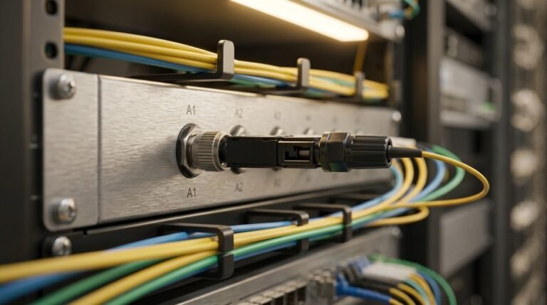
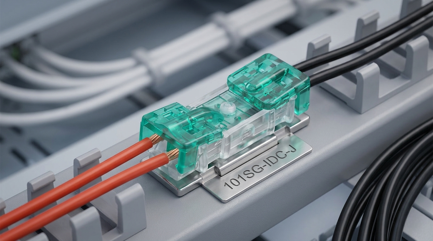
To begin with, the 101SG Inline Connector is a highly advanced splicing solution designed to bridge solid copper communication conductors with maximum efficiency. Specifically, it utilizes an insulation displacement contact (IDC) mechanism to cut through plastic coatings. This design element eliminates the tedious requirement of stripping wires prior to splicing. Consequently, technicians save valuable field time during massive cable rollouts. In addition, the internal chamber is completely pre-filled with an organic, hydrophobic sealing gel. This proprietary gel formulation immediately surrounds the contact point during the crimping process. Accordingly, it acts as an impenetrable barrier against water molecules and atmospheric oxygen, which prevents corrosion.
Furthermore, the physical architecture of the 101SG Inline Connector is engineered to withstand extreme physical stress. The external shell consists of high-density polycarbonate that offers excellent impact resistance. This thermoplastic material is specifically chosen because it does not crack under intense cold or distort under solar heat. To illustrate, field deployments often expose telecommunication cables to direct sunlight and sub-zero temperatures. Therefore, maintaining outer shell integrity is paramount to keeping the inner gel sealing active. Within this protective dome, dual-contact blades made of tin-plated phosphor bronze establish a permanent gas-tight connection with the wire. Consequently, the transmission signal remains clean and free of noise over a broad spectrum of frequencies.
Historically, splicing telephone lines required extensive soldering or manual twisting wrapped in vinyl tape. However, those legacy methods proved highly susceptible to thermal expansion and humidity. In contrast, the modern IDC blade system inside the 101SG Inline Connector creates a consistent mechanical spring force. This spring force constantly squeezes the copper conductor, adapting naturally to thermal expansion cycles. Therefore, the contact resistance of the joint remains extremely low and stable over the product’s entire lifespan. This makes it an ideal fit for modern high-speed DSL lines and signaling networks where even micro-ohms of resistance variation can cause data packet loss.
Key Specifications and Mechanical Integrity
When evaluating hardware for critical infrastructure, engineers must review exact mechanical tolerances and material limits. Specifically, the compatibility of wire gauges is a foundational parameter for any splice design. The typical IDC slot is precisely calibrated to accept solid copper conductors ranging from 19 AWG to 26 AWG. This versatile range ensures that field technicians do not need to carry multiple connector styles for standard telecom drop wires. Moreover, the entry ports of the housing are constructed with wide funnels. This structural feature guides the insulated wire straight into the shearing blades, minimizing misalignments during fast-paced field operations.
In addition to wire gauge versatility, the tensile strength of the completed splice must meet strict international standards. For example, joint failures usually occur when thermal contraction pulls cables apart. To prevent this hazard, the inner housing of the connector incorporates integrated strain-relief bars. These bars grab the outer plastic jacket of the incoming wires when the housing is fully depressed. Consequently, any mechanical tension applied to the cable is absorbed by the robust outer sheath rather than the delicate electrical contact point. This design approach guarantees that the electrical splice survives accidental pulls, heavy winds, and cable movement inside outdoor utility boxes.
Furthermore, the chemistry of the hydrophobic sealant gel inside the connector deserves thorough analysis. This gel is formulated from polybutene materials that retain their high viscosity across a very wide temperature spectrum. It does not leak out of the housing at elevated summer temperatures, nor does it crystallize and break when freezing winter conditions arrive. Specifically, the gel exhibits excellent dielectric properties, ensuring that no leakage currents pass between adjacent contact elements. This high level of insulation resistance is vital for preventing crosstalk in multi-pair communication cables, thereby keeping communication lines perfectly isolated and clean.
Electrical Resistance of the 101SG Inline Connector
The core objective of any electrical junction is to facilitate the flow of current with minimal resistance. Consequently, the contact resistance of the 101SG Inline Connector is engineered to remain well under the strict thresholds set by global standards bodies. For instance, organizations such as the Institute of Electrical and Electronics Engineers (IEEE) specify rigorous testing methods for mechanical wire splices. During these standardized evaluations, the initial contact resistance of a newly crimped joint is typically measured in the low milliohm range. This excellent performance is directly attributable to the sharp, dual-blade phosphor bronze contacts that cleanly slice through the wire insulation.
Furthermore, the physical pressure exerted by the IDC slot is carefully calculated to deform the copper conductor slightly. This controlled deformation is known as cold welding, which creates a gas-tight interface. Specifically, by excluding oxygen from the contact surfaces, the formation of non-conductive copper oxide films is completely prevented. This is a crucial factor for long-term electrical stability, as copper oxide is highly resistive and can degrade signals over time. Consequently, the electrical path within the 101SG Inline Connector remains highly conductive, even after years of exposure to corrosive salt spray or industrial atmospheres. Therefore, network designers can deploy these components with absolute confidence in challenging coastal or urban environments.
Similarly, the low contact resistance of this connector directly translates into minimal signal attenuation. In modern communication lines, high-frequency signals are highly sensitive to any impedance discontinuities. If a splice joint introduces a sudden jump in resistance, it can reflect a portion of the signal back to the source. This phenomenon, known as return loss, degrades the overall bandwidth of the link. However, the streamlined internal design of the 101SG Inline Connector minimizes these impedance jumps. Consequently, high-speed data transmission is preserved without distortion, ensuring that end-users enjoy stable internet and signaling connections without interruption.
Understanding Structural Components of Connectors
To fully appreciate the engineering behind modern splice technology, we must deconstruct the connector into its individual parts. Each component plays a specific role in maintaining the mechanical and electrical integrity of the joint. At the center of the system lies the phosphor bronze contact plate. Phosphor bronze is selected for its unique combination of electrical conductivity, high tensile strength, and excellent fatigue resistance. Unlike standard brass, phosphor bronze retains its spring-like tension over decades, continuing to exert constant force on the spliced wires. This steady pressure is vital for resisting the mechanical stresses of wind vibration and thermal shifting.
To further enhance conductivity and prevent oxidation, the phosphor bronze contact is plated with a thick layer of high-purity tin. Tin is a relatively soft metal that deforms under the intense pressure of the crimping process. This deformation fills any microscopic voids between the copper wire and the contact blade, increasing the effective surface area of the connection. Consequently, this metallurgical interaction dramatically reduces the electrical contact resistance. In addition, the tin plating acts as a sacrificial barrier, protecting the underlying copper-alloy blade from galvanic corrosion when exposed to moisture. Therefore, this dual-metal system is highly effective in ensuring long-term durability.
Surrounding this metal core is the clear, impact-resistant polycarbonate housing. The transparency of the shell is a crucial feature for quality control, allowing installers to visually inspect the spliced wires. Specifically, technicians can easily verify that the copper conductors have penetrated the IDC blades fully and are seated correctly at the back of the connector. This visual confirmation eliminates guesswork in the field, reducing the occurrence of faulty splices. Finally, the outer entry ports are designed with narrow sealing rings. These rings pinch the wire jackets upon crimping, creating a secondary mechanical seal that prevents the hydrophobic gel from escaping under pressure.
EPCOM Quality Standards in Manufacturing
As a leading supplier of network infrastructure materials, EPCOM maintains rigorous quality control standards across all its production lines. Specifically, every batch of connectors undergoes extensive mechanical stress testing and electrical evaluation. This ensures that every unit delivered to the field performs flawlessly under demanding industrial conditions. For example, during factory testing, sample connectors are subjected to rapid thermal cycling, vibrating tables, and complete water immersion. By simulating decades of environmental wear in a compressed timeframe, engineers can verify the long-term reliability of the physical seals and electrical contacts.
Furthermore, EPCOM’s manufacturing facilities utilize automated optical inspection (AOI) systems to check the alignment of the internal contact blades. Even a tiny fraction of a millimeter of misalignment could cause a contact blade to slice too deeply into a copper wire, weakening its physical strength. Alternatively, a misaligned blade might fail to pierce the insulation completely, resulting in an open circuit. To prevent these defects, high-resolution cameras inspect every single housing before it is filled with sealant gel and packaged. Consequently, the defect rate of these precision-engineered units is virtually zero, making them highly trusted by major telecommunications utility operators worldwide.
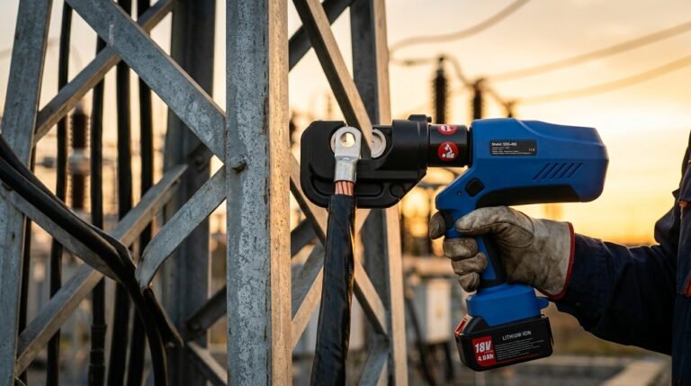
In addition to standard splicing solutions, EPCOM manufactures specialized heavy-duty components for high-voltage power networks. For instance, when dealing with larger electrical cables, technicians utilize advanced insulation piercing technology. To learn more about these heavy-duty systems, engineers can refer to the JBC Insulation Piercing Connector, which utilizes a similar shear-head bolt mechanism to establish secure, weatherproof connections on low-voltage aerial lines. By applying these rigorous quality standards across both telecom and power product lines, the company ensures that its infrastructure hardware can withstand the most demanding physical environments over long operational lifespans.
Thermal Stability of the 101SG Inline Connector
Outdoor utility hardware is constantly subjected to seasonal temperature swings that cause materials to expand and contract. Consequently, the 101SG Inline Connector is designed with thermal stability as a core engineering parameter. Specifically, the expansion coefficient of the polycarbonate outer shell is carefully matched to that of the internal metallic components. This precise alignment prevents the development of internal gaps during extreme temperature transitions. If the plastic housing expanded much faster than the bronze contact blades, it could create tiny voids. These voids would allow the protective gel to migrate away from the splice, exposing the copper wire to ambient air.
To verify this thermal stability, engineers conduct rigorous temperature testing in specialized environmental chambers. The connectors are repeatedly cycled between extreme temperatures, ranging from -40 degrees Celsius to +80 degrees Celsius. This intense test simulates the harshest environments on earth, from arctic winters to desert heat waves. Throughout these rapid thermal cycles, the contact resistance of the joint is continuously monitored to detect any electrical instability. Remarkably, the advanced mechanical design of the IDC blades ensures that the contact resistance remains stable, showing virtually no variation even during the most severe temperature drops.
Furthermore, the physical behavior of the hydrophobic gel remains highly stable under these extreme thermal conditions. In high-temperature environments, some low-grade sealing gels can break down, turning into a thin liquid that drains out of the connector. Once the gel is lost, the splice is highly vulnerable to moisture ingress and subsequent corrosion. However, the premium polymer gel used by EPCOM is engineered to resist thermal degradation, maintaining its thick, gel-like consistency even at elevated operating temperatures. Conversely, in extreme cold, the gel remains flexible and does not crack, ensuring that the waterproofing barrier remains completely intact year-round.
Comparing Different Inline Connector Series
Depending on the specific requirements of a network rollout, field engineers may need to choose between several types of inline splice joints. For example, while some applications demand three-wire splicing capabilities, others only require a simple two-wire bridge. To meet these varied needs, EPCOM offers a versatile family of splicing solutions, each optimized for different wire diameters and environmental conditions. Specifically, the U1R Inline Connector is a widely utilized alternative that features a compact design, making it ideal for tight spaces inside dense splice closures.
Similarly, for other specialized communication setups, the U1B Inline Connector provides a reliable bridging option with its own unique terminal spacing configuration. These different connector series allow network planners to select the exact hardware model that matches their cabling architecture. Meanwhile, for heavy-duty power lines and overhead electrical cables, standard telecom connectors are not suitable due to the much larger wire gauges involved. In those high-current scenarios, utilities rely on robust mechanical clamps, such as the JBT Parallel Groove Connector, to secure and join heavy power conductors safely.
To help engineers choose the best connector for their projects, the table below provides a detailed comparison of the key specifications and primary applications for each of these major connectivity models:
| Connector Model | Supported Wire Gauge (AWG / mm²) | Internal Sealant Type | Primary Application Field | Maximum Current Capacity |
|---|---|---|---|---|
| 101SG Inline Connector | 19 – 26 AWG (Solid Copper) | Premium Hydrophobic Gel | Telecom Splicing & Signal Wiring | Low-current signaling (up to 2A) |
| U1R Inline Connector | 19 – 24 AWG (Solid Copper) | Waterproof Silicone Sealant | Outdoor Telephone Drop Wire Joints | Low-current signaling (up to 2A) |
| U1B Inline Connector | 16 – 22 AWG (Solid/Stranded) | Moisture-resistant Gel | Industrial Alarm & Control Systems | Control Signals (up to 5A) |
| JBT Parallel Groove Connector | 16 – 150 mm² (Al/Cu Conductor) | Antioxidant Joint Compound | Power Grid Distribution Lines | High Voltage Power (up to 400A) |
| JBC Insulation Piercing Connector | 1.5 – 150 mm² (Insulated Cable) | Weatherproof Polymer Seal | Low-Voltage Aerial Bundled Cables | High Current Power (up to 250A) |
Installation Practices for the 101SG Inline Connector
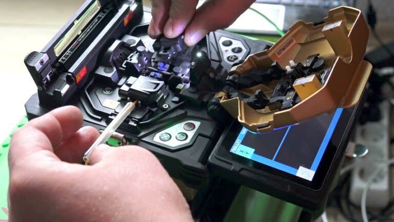
To achieve the lowest possible contact resistance and guarantee a waterproof seal, installers must follow precise installation guidelines. First, the two copper wires to be spliced should be aligned and cut cleanly. It is critical to use a sharp cutting tool to ensure the wire ends are perfectly square, without any jagged edges or squashed metal. In addition, technicians must not attempt to strip the plastic insulation off the wires. The insulation displacement contact (IDC) blades inside the 101SG Inline Connector are specifically engineered to cut through standard plastic jacketing. Stripping the wires manually before insertion can weaken the copper conductor, leading to mechanical failure.
Next, the unstripped wires are inserted into the entry ports of the connector. The technician must push the wires all the way to the back of the chamber. Because the housing is made of transparent polycarbonate, the installer can easily look through the plastic shell to confirm that both wires are fully seated. This visual verification step is crucial, as partially inserted wires may not engage with both contact blades, resulting in a weak or open circuit. Once the wires are correctly positioned, the technician places the connector into a specialized crimping tool. Using standard hand pliers is highly discouraged, as they do not apply force evenly across the housing.
Finally, the technician squeezes the crimping tool until the colored cap of the connector is fully depressed, level with the clear body. This motion drives the phosphor bronze contact blades down through the wire insulation, establishing a solid electrical connection. Simultaneously, the mechanical pressure squeezes the hydrophobic gel, forcing it to fill every remaining pocket of air inside the housing. This complete displacement of air ensures that no moisture can ever reach the electrical splice. Once the crimp is complete, the technician should perform a gentle pull test on the wires to verify that the integrated strain-relief mechanism has securely gripped the cable jackets.
Safe Handling and Environment Considerations
Deploying electrical connectors in outdoor environments requires careful consideration of local environmental hazards. Specifically, ultraviolet (UV) radiation from sunlight can rapidly degrade low-grade plastics, causing them to become brittle and yellow. Consequently, EPCOM utilizes a UV-stabilized polycarbonate for the outer shell of all its connectors. This specialized formulation contains additives that absorb harmful UV rays, protecting the polymer chain from breaking down. As a result, the outer housing remains strong and flexible, even after decades of continuous exposure to direct sunlight on utility poles.
Furthermore, chemical exposure is a major concern in industrial areas and coastal zones. For example, sulfur dioxide from industrial plants and sodium chloride from ocean spray can create highly corrosive atmospheric conditions. If these corrosive agents penetrate the connector housing, they can dissolve the tin plating on the contacts, leading to rapid electrical failure. However, the premium hydrophobic gel used in the 101SG Inline Connector is chemically inert, meaning it does not react with acids, bases, or salts. Consequently, the gel acts as an absolute seal, isolating the electrical contact point from the external chemical environment.
Similarly, the physical placement of splice joints should be planned to minimize exposure to standing water. While these connectors are rated for high humidity and occasional splashing, they are not designed for permanent underwater submersion. Therefore, installers should position spliced joints inside elevated enclosures or weatherproof junction boxes whenever possible. When splicing inside underground vaults, the connectors should be elevated above the maximum expected water level to ensure they remain dry. By combining proper physical placement with high-quality hardware, utility operators can prevent water damage and ensure continuous network uptime.
Why Select EPCOM Connectors for Telecom Grids?
When planning large-scale infrastructure projects, purchasing managers must balance initial procurement costs against long-term maintenance expenses. While cheaper, generic connectors may seem attractive initially, they often exhibit high failure rates in the field. Consequently, service providers suffer from frequent service outages, leading to costly technician dispatches and poor customer satisfaction. In contrast, investing in premium EPCOM connectors dramatically reduces maintenance overhead. Because these components are manufactured to the highest tolerances, they achieve a virtually zero-failure rate, saving operators thousands of dollars in long-term operational costs.
Furthermore, the physical design of the connector significantly boosts technician productivity in the field. The fast, strip-free installation process allows crews to complete splicing tasks in a fraction of the time required by legacy methods. This increased efficiency is particularly valuable during emergency repair operations following severe storms or fiber-optic cable cuts. By enabling faster restorations, EPCOM hardware helps service providers meet strict service-level agreements (SLAs) and maintain a highly reliable network reputation. Therefore, selecting high-quality splicing components is a wise decision for both financial managers and network engineers.
In addition, EPCOM supports its global customer base with comprehensive technical documentation and responsive engineering support. Whether designing a local telephone network or a massive regional smart grid, operators can access detailed specifications, installation videos, and environmental test reports. This technical transparency is a key advantage, as it allows project planners to verify that every component meets the specific regulatory requirements of their region. Consequently, from initial planning to final field deployment, the manufacturer serves as a reliable partner in building durable, high-performance communication systems.
Industry Applications of 101SG Inline Connector Units
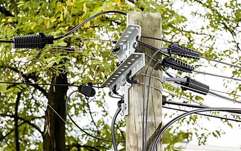
The versatility and high reliability of the 101SG Inline Connector make it a preferred choice across a wide range of industrial sectors. Specifically, in the telecommunications industry, these components are widely deployed in the local loop, connecting individual subscriber drop wires to main distribution cables. Because these aerial drops are exposed to heavy wind vibration and rain, the connector’s integrated strain-relief and hydrophobic gel are essential for maintaining stable telephone and internet connections. Consequently, major telecom operators rely on these devices as their standard splicing hardware for copper infrastructure.
Furthermore, industrial automation and control systems frequently utilize these high-performance splice joints. Modern manufacturing plants contain thousands of sensors, actuators, and limit switches that feed data back to central programmable logic controllers (PLCs). Because these control signals operate at low voltages, they are highly sensitive to electrical noise caused by loose connections. However, the gas-tight IDC contacts of the 101SG Inline Connector ensure a permanent, vibration-resistant connection that completely eliminates intermittent signal dropouts. Consequently, factory automation engineers trust these components to maintain continuous production line operation.
Similarly, security and surveillance networks benefit greatly from these precise splicing systems. Outdoor closed-circuit television (CCTV) cameras and perimeter security sensors are often installed in remote, exposed locations, such as utility poles or perimeter fences. Splicing power and control wiring for these systems requires a compact, highly reliable joint that can fit inside small camera mounts. By using the 101SG Inline Connector, security technicians can establish secure, weatherproof connections quickly, ensuring that critical security feeds remain active and uninterrupted, regardless of local weather conditions.
Maintenance Protocol for Inline Connections
While high-quality mechanical splices are designed to be maintenance-free, establishing a proactive inspection protocol can help identify potential network issues before they cause service outages. First, technicians should perform regular visual inspections of outdoor splice enclosures. This routine check allows crews to verify that the outer enclosures remain structurally sealed and that no water has accumulated inside the boxes. If moisture is detected inside a closure, the technician should identify the source of the leak and replace any damaged seals immediately to protect the inner wire splices.
Furthermore, during routine network testing, technicians can measure the loop resistance of critical communication circuits. If a particular line exhibits a sudden increase in electrical resistance, it may indicate a degraded splice joint or a damaged cable section. By using an optical time-domain reflectometer (OTDR) or a high-precision digital multimeter, crews can pinpoint the exact location of the resistance jump. If a splice is found to be faulty, it should be cut out and replaced with a new 101SG Inline Connector, ensuring that the electrical circuit is restored to its optimal, low-resistance state.
Finally, keeping detailed records of all network splices is highly recommended for long-term grid management. When a technician installs a new connector in the field, they should log the location, wire gauge, and date of installation in a central database. This historical data is incredibly valuable for troubleshooting future network anomalies and planning targeted infrastructure upgrades. By combining premium hardware with rigorous maintenance practices, network operators can maximize the lifetime of their copper infrastructure, ensuring decades of reliable, high-speed data transmission for their subscribers.