
FC Optical Attenuator: High Precision Tech
FC Optical Attenuator is the cornerstone of precision signal management in high-density fiber optic communication environments. At EPCOM, we recognize that maintaining the delicate balance of light power is vital for network longevity. Consequently, engineers utilize these components to reduce optical power levels without distorting the underlying signal waveform. Fiber optic systems often face challenges related to receiver saturation. For instance, if the light signal is too strong, the sensitive photodetectors can become overwhelmed. Therefore, the integration of a reliable attenuator ensures that the data transmission remains crisp and error-free. Furthermore, these devices provide the necessary control for testing and calibration. In this expansive analysis, we will explore the technical nuances, applications, and strategic advantages of implementing these tools in your infrastructure.
Optical networks have evolved rapidly over the last decade. As a result, the demand for high-performance components has skyrocketed. EPCOM remains at the forefront of this evolution by providing robust solutions. Transitioning from legacy systems to modern high-speed architectures requires meticulous planning. Specifically, managing power budgets is a critical step in this transition. By using an FC Optical Attenuator, technicians can simulate long-distance cable runs within a controlled lab setting. Moreover, this flexibility allows for rigorous stress testing of network equipment. Nevertheless, one must select the correct attenuation value to achieve optimal results. If the attenuation is too high, the signal disappears. Conversely, if it is too low, the hardware risks damage.
Understanding the FC Optical Attenuator Mechanics
The fundamental principle of an FC Optical Attenuator involves the absorption or scattering of light. However, the device must achieve this without introducing unwanted reflections. To put it another way, back-reflection can severely degrade laser performance. EPCOM engineers focus on minimizing the Return Loss while ensuring the Insertion Loss is precisely controlled. Most modern units utilize a doped fiber or a gap-loss technique. With this in mind, the “FC” designation refers to the Ferrule Connector type. This connector is well-known for its threaded body and vibration-resistant design. Therefore, it is the preferred choice for telecommunications and industrial applications where stability is paramount.
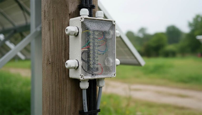
Furthermore, the physical construction of these attenuators allows for easy integration. They often feature a male-to-female configuration, commonly known as a “plug-style” design. Because of this, they can be inserted directly between a patch cord and a transceiver. In addition, they are compatible with both Single Mode and Multimode fibers. Consequently, the versatility of the FC Optical Attenuator makes it a staple in every technician’s toolkit. EPCOM ensures that every unit meets stringent international standards. This commitment to quality prevents unexpected downtime in critical data links. Likewise, using standardized components simplifies the maintenance process for large-scale deployments.
Strategic Benefits of an FC Optical Attenuator
One major benefit is the prevention of bit errors. When an optical receiver is over-saturated, it begins to drop packets. Nevertheless, adding an attenuator brings the power back into the “sweet spot” of the detector. EPCOM designs these products to handle various power levels, ranging from 1dB to 30dB. In light of this, customized solutions are available for specialized hardware. Another advantage is the durability of the threaded FC connection. Unlike snap-on connectors, the FC type stays secure even under mechanical stress. This reliability is why many providers pair them with an ST Fiber Optic Adaptor in hybrid environments.
Moreover, cost-effectiveness is a significant factor. Replacing a burnt-out transceiver is expensive. On the other hand, a simple attenuator costs very little. Thus, using an FC Optical Attenuator acts as an insurance policy for your expensive networking hardware. Transitioning to higher speeds, such as 40G or 100G, makes this even more important. High-speed lasers are often more sensitive to power fluctuations. Therefore, EPCOM recommends verifying power levels at every stage of the installation. Consistent monitoring leads to a more resilient network overall.
Signal Stability Comparison
Figure 1: Comparison of signal integrity with and without proper attenuation levels.
Optimizing Connectivity with SC ST Patch Cord Solutions
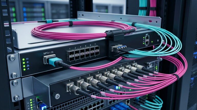
Connectivity is more than just plugging in a cable. It is about the quality of the glass and the precision of the ferrule. For example, when connecting an FC Optical Attenuator to a distribution frame, the choice of patch cable is vital. Many EPCOM customers find that using a high-quality SC ST Patch Cord allows for seamless transitions between different connector standards. Because fiber networks often use a mix of SC and ST ports, these patch cords provide necessary flexibility. Furthermore, a well-manufactured cable reduces noise. If the cable is substandard, even the best attenuator cannot fix the signal issues. Therefore, EPCOM emphasizes using premium grade materials for all jumpers.
In addition, the physical environment affects performance. Dust is the enemy of fiber optics. Consequently, EPCOM ships all attenuators and patch cords with protective dust caps. Technicians should always clean the end-faces before mating. This practice prevents permanent damage to the glass. To put it another way, cleanliness is as important as signal attenuation. By maintaining a clean environment, you extend the life of your FC Optical Attenuator. Furthermore, the use of high-quality ferrules ensures that the alignment is perfect every time. Perfect alignment means lower insertion loss and higher reliability.
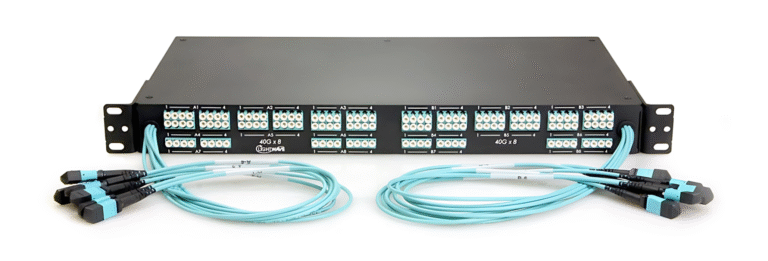
The Vital Role of the MPO MTP Optical Power Meter
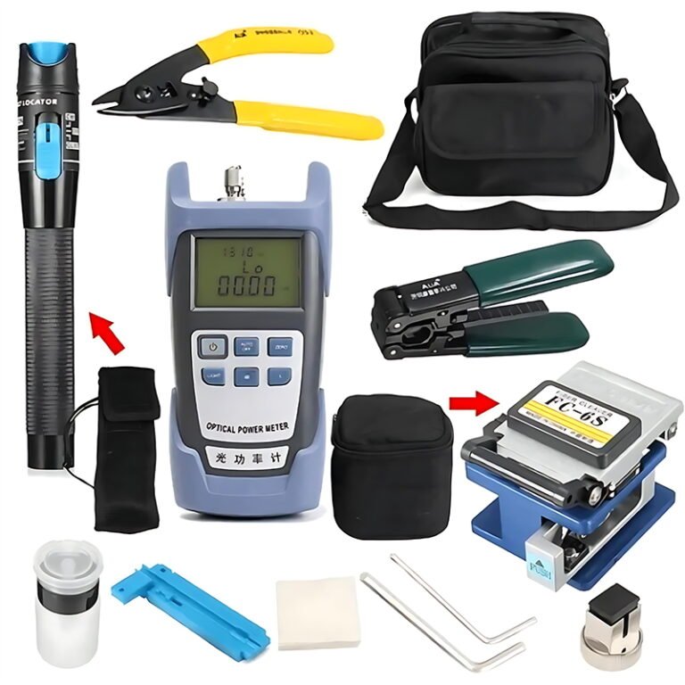
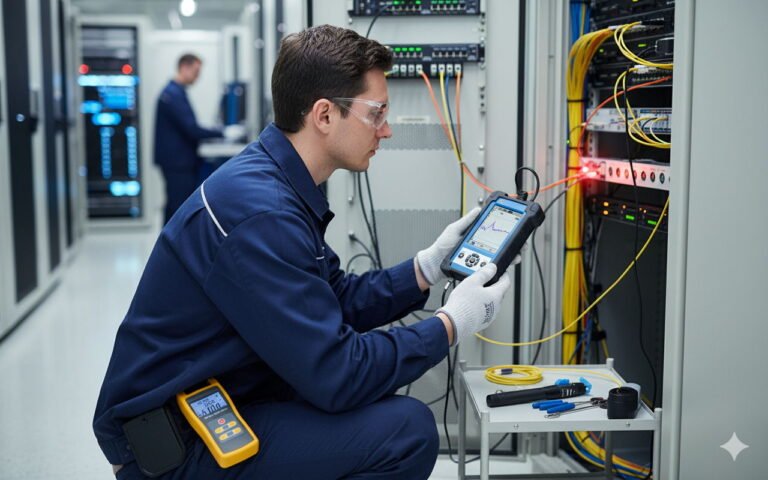
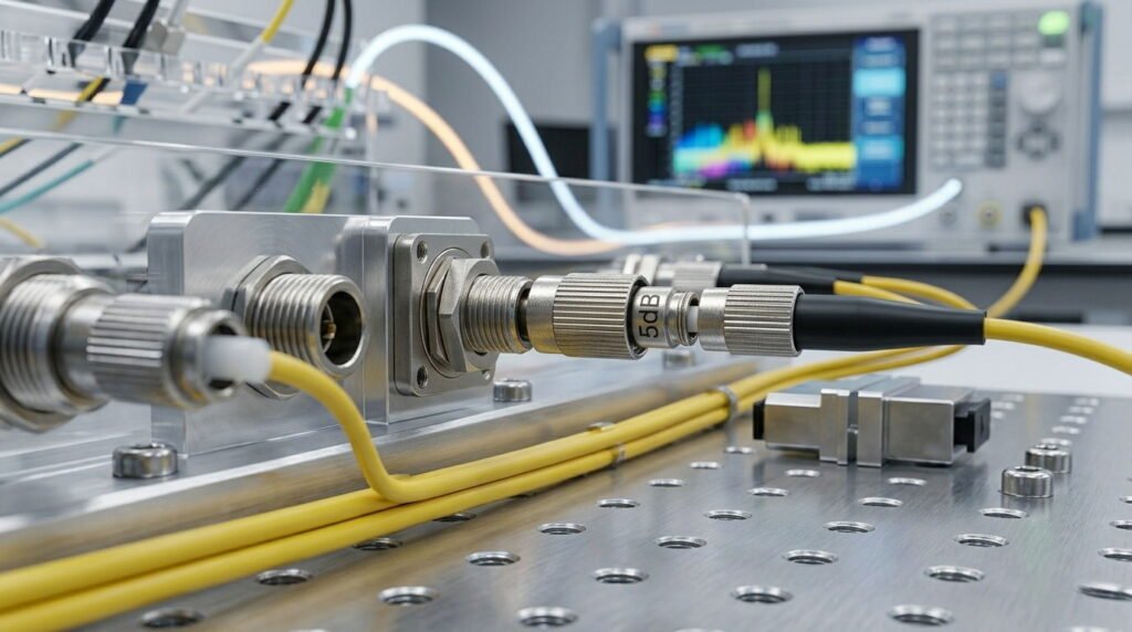
Measurement is the key to accuracy in any optical deployment. Without a way to verify the power levels, you are working in the dark. For this reason, EPCOM recommends using an MPO MTP Optical Power Meter. This specialized tool allows for the simultaneous testing of multiple fibers. When you install an FC Optical Attenuator, you must measure the output to confirm it matches the desired specification. Specifically, if you ordered a 10dB attenuator, the meter should show exactly a 10dB drop compared to the source. Any discrepancy suggests a dirty connector or a faulty component. Consequently, having the right test equipment is non-negotiable for professional installers.
Moreover, modern power meters are incredibly portable and easy to use. They support various wavelengths, such as 1310nm and 1550nm. These are the standard frequencies used in long-haul networks. With this in mind, EPCOM ensures that all testing tools are calibrated to ITU-T international standards. Using calibrated tools prevents errors during the commissioning phase of a project. Furthermore, documenting these measurements provides a baseline for future troubleshooting. If a network failure occurs later, you can compare current readings against the original installation data. This methodology saves hours of diagnostic time.
Technical Specifications for FC Optical Attenuator Selection
Selecting the right hardware requires a clear understanding of the specs. EPCOM provides a wide range of options to suit diverse needs. Below is a comparison table to help you identify the best fit for your specific application. Note the differences in attenuation range and operating temperatures. These factors are critical for outdoor installations where climate control is not possible.
| Feature | Plug-Style Attenuator | Variable Attenuator | Inline Attenuator |
|---|---|---|---|
| Attenuation Range | Fixed (1-30dB) | Adjustable (0-60dB) | Fixed (5-20dB) |
| Connector Type | FC/UPC or FC/APC | FC Threaded | Pigtailed FC |
| Return Loss | >50dB (UPC) | >45dB | >50dB |
| Operating Temp | -40 to +75°C | -25 to +70°C | -40 to +80°C |
| Primary Use Case | Receiver Protection | Lab Testing | Permanent Install |
How to Install an FC Optical Attenuator Correctly
Installation might seem simple, but it requires precision. First, identify the direction of the light signal. The FC Optical Attenuator is usually placed at the receiver end. Placing it at the transmitter end can sometimes cause issues with laser stability due to back-reflections. Second, ensure you are using the correct polish type. FC connectors come in UPC (Blue/Metal) and APC (Green). EPCOM warns that mixing these will cause significant signal loss and might damage the connectors. Therefore, always check the color coding and labels before connection. Consequently, verifying the polish type is the most common step overlooked by beginners.
Once the type is confirmed, clean the connector faces. Use an isopropyl alcohol wipe or a dedicated fiber cleaner. After cleaning, insert the male end of the FC Optical Attenuator into the adapter. Tighten the threaded nut firmly but do not over-tighten. Over-tightening can crack the ceramic ferrule. Next, connect the patch cable to the female end of the attenuator. Finally, use your power meter to check the levels. If the reading is within the expected range, the installation is successful. EPCOM recommends a final inspection with a fiber scope to ensure no dust was introduced during the process. Continuous monitoring after installation is also a good practice for the first 24 hours.
Advanced Network Design with FC Optical Attenuator Units
In high-density data centers, space is at a premium. Consequently, the compact size of the plug-style FC Optical Attenuator is a major benefit. These small devices do not require extra rack space. They simply become part of the cabling. However, in larger architectures, engineers might prefer variable optical attenuators (VOAs). VOAs allow for real-time adjustment of power levels. This is particularly useful in Wavelength Division Multiplexing (WDM) systems. In such systems, different wavelengths might require different levels of attenuation. EPCOM provides solutions for both scenarios, ensuring that network designers have the tools they need for complex environments.
Furthermore, consider the impact of environmental factors. Temperature swings can cause physical expansion or contraction in fiber components. Nevertheless, a high-quality FC Optical Attenuator from EPCOM is designed to be thermally stable. This means the attenuation value remains constant regardless of the weather. This stability is achieved through precise manufacturing and the use of high-grade ceramics. In addition, these components are tested against vibration and shock. Because many fiber lines run along railways or busy roads, vibration resistance is essential. Transitioning to EPCOM hardware ensures that your signal remains steady even in harsh conditions.
Compliance and Standards for the FC Optical Attenuator
Every FC Optical Attenuator must adhere to strict industry guidelines. Specifically, the Telcordia GR-910 standard governs the performance of these devices. EPCOM ensures that all products meet or exceed these requirements. This includes testing for durability over hundreds of mating cycles. If an attenuator fails after only ten uses, it is a liability. For this reason, we use high-strength metal housings for our FC products. Furthermore, compliance with RoHS standards ensures that our manufacturing is environmentally friendly. By choosing EPCOM, you are supporting sustainable and reliable technology.
In addition, the FC Optical Attenuator is often used in medical and military applications. In these sectors, failure is not an option. Consequently, the rigorous testing protocols we follow are designed to simulate extreme conditions. Whether it is high humidity or extreme cold, our attenuators perform consistently. Moreover, the traceability of our components allows for easy auditing. Each unit is batch-tested, and the data is archived. This level of transparency is why EPCOM is a trusted name in global telecommunications. To put it another way, we don’t just sell parts; we sell peace of mind.
Common Issues with FC Optical Attenuator Usage
Even with the best hardware, problems can arise. The most common issue is “Ghosting” or unwanted reflections. This happens when the FC Optical Attenuator is not seated correctly. Another problem is the accumulation of debris inside the female port. If you notice a sudden drop in signal quality, check the attenuator first. EPCOM technicians recommend a regular cleaning schedule for all fiber ports. In addition, check for physical damage to the threads. If the threads are stripped, the connector will not sit flush. Consequently, this leads to air gaps and massive signal loss.
Furthermore, sometimes the attenuation value is labeled incorrectly by cheaper manufacturers. Using a non-verified FC Optical Attenuator can lead to confusing test results. Therefore, EPCOM individually tests each unit to guarantee the dB rating. If you suspect an attenuator is faulty, swap it with a known good unit. If the problem disappears, the original unit was the culprit. Transitioning to a systematic troubleshooting approach saves time. Moreover, always keep a few spare attenuators in various values (5dB, 10dB, 15dB) on hand. This allows for quick adjustments during an emergency outage. Having the right parts ready is the hallmark of a prepared network engineer.
The Future of Signal Management and EPCOM
As we look toward 800G and beyond, the role of the FC Optical Attenuator will continue to change. New fibers, like hollow-core fiber, might change how we think about light absorption. However, the need for precise power control will remain a constant. EPCOM is currently researching next-generation materials to further reduce back-reflection. Our goal is to create attenuators that are virtually invisible to the rest of the system. With this in mind, we are also looking at integrating smart sensors into our attenuators. Imagine a device that can report its own power levels back to a central hub. This is the future we are building.
In conclusion, the FC Optical Attenuator is more than just a simple resistor for light. It is a precision-engineered component that ensures the stability of the global internet. From protecting receivers to enabling complex lab simulations, its utility is unmatched. By combining these attenuators with ST Fiber Optic Adaptor units and high-quality patch cords, you create a robust foundation. EPCOM is proud to be your partner in this journey. We provide the expertise and the hardware to keep your data moving at the speed of light. Furthermore, our commitment to technical excellence ensures that every connection you make is a strong one. Consequently, when you think of fiber optics, think of EPCOM for all your attenuation needs.
Final thoughts on maintenance: remember that a fiber network is a living system. It requires care and attention. Regularly inspecting your FC Optical Attenuator will prevent major headaches down the road. Furthermore, stay updated on the latest standards from the Telecommunications Industry Association. Knowledge is the most powerful tool in your belt. Combined with EPCOM hardware, you are ready for any networking challenge the future may hold. Thank you for choosing EPCOM as your source for high-performance optical solutions. We look forward to supporting your next big project with the best attenuators on the market today.