Fiber Optic Longitudinal Slitter: Cable Prep
Fiber Optic Longitudinal Slitter technology represents the backbone of modern telecommunication network rollouts. Consequently, field technicians rely heavily on these precise tools to gain seamless mid-span access to optical fibers without interrupting active network channels. When deploying fiber to the home (FTTH) or connecting massive enterprise networks, cable preparation is the most critical phase. Therefore, choosing a robust, high-performance slitting device determines the integrity of your entire physical link. The following discussion explores how these specialized cutters operate. Additionally, we will explain how to integrate them with companion equipment to achieve flawless splicing. Ultimately, our goal is to show you how to maximize installation speed while protecting fragile glass cores.
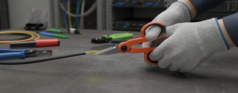
Furthermore, fiber optic cable construction has evolved rapidly. Modern cables feature high-density outer jackets made of medium-density polyethylene (MDPE) or high-density polyethylene (HDPE). These hard polymers safeguard the internal components against water ingress, extreme temperatures, and mechanical stress. However, these tough protective layers pose a major challenge during termination or splicing. Traditional cutting tools often crush the outer sheath, which can easily damage the delicate buffer tubes inside. Conversely, a dedicated longitudinal slitting tool slices cleanly through the sheath parallel to the cable axis. This targeted cutting action allows for easy peeling, exposing the inner components safely. By using tools from EPCOM, technicians can easily execute these delicate operations in any field environment.
Why Choose a Fiber Optic Longitudinal Slitter?
In telecommunication infrastructure, time translates directly to profitability. Consequently, tools that reduce preparation time while maintaining high safety margins are highly valuable. The primary function of a Fiber Optic Longitudinal Slitter is to provide precise longitudinal cuts along the outer jacket of a fiber optic cable. This specific slitting orientation is highly superior to standard circumferential ringing cuts. Ringing cuts are useful for cable ends, but they present significant risks when performing mid-span access. Specifically, a circumferential cut on a tense, live cable can lead to accidental radial cutting. This mistake can instantly sever inner active buffer tubes, resulting in expensive network downtime.
Therefore, a Fiber Optic Longitudinal Slitter is the preferred tool for high-density loose tube cables. By slitting the jacket lengthwise, technicians can peel back the outer sheath like a banana peel. This method is incredibly safe. In addition, it provides a larger, cleaner working area to extract individual buffer tubes. Furthermore, this process is indispensable for drop cable installations in residential areas. When a technician needs to tap into a single fiber within a 144-core cable, they do not need to cut the entire cable. Instead, they use the Fiber Optic Longitudinal Slitter to access only the target tube. Consequently, the remaining 143 fibers continue to transmit data without a microsecond of interruption.
Moreover, the versatility of these slitters makes them suitable for various cable sheath materials. For instance, they handle standard PVC, robust polyurethane, and thick polyethylene with ease. Some advanced models can even score the thin metal tape found in corrugated steel-armored cables. Consequently, field crews do not need to carry a massive array of different tools. A single, well-designed slitting tool from EPCOM can handle multiple cable types. This versatility reduces tool bag weight, simplifies training, and guarantees consistent results across different construction crews.
Mechanics of the Fiber Optic Longitudinal Slitter
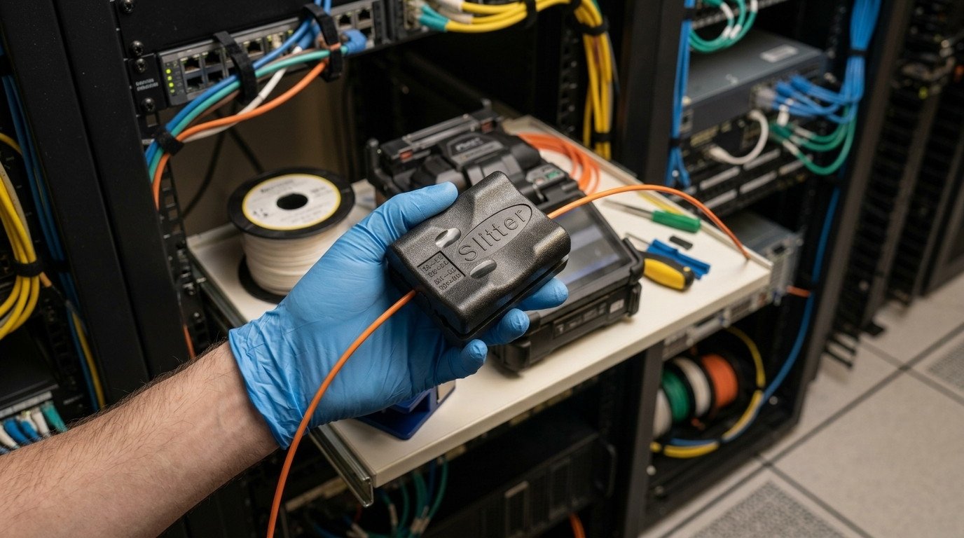
Understanding the mechanical design of a Fiber Optic Longitudinal Slitter helps technicians make better decisions in the field. At its core, the tool features a set of ultra-sharp blades positioned within a guide channel. These blades are manufactured from high-grade materials such as hardened high-carbon steel or tungsten carbide. Consequently, they maintain their sharp cutting edges even after hundreds of cuts through abrasive high-density polyethylene. The sharpness of the blade is critical. A dull blade requires more pulling force, which increases the likelihood of slipping and causing structural damage.
Furthermore, blade depth adjustability is the most critical mechanical feature of any slitting tool. To ensure the blades do not touch the inner buffer tubes, technicians must set the cutting depth precisely. Most high-quality slitters use a micrometric dial or interchangeable guide keys to control blade extension. For instance, if a cable jacket is 1.5 millimeters thick, the technician will set the slitter depth to approximately 1.3 millimeters. This setting leaves a tiny, uncut sliver of polymer that easily tears open during the peeling stage. As a result, the blade never makes contact with the fragile protective materials inside, ensuring 100% safety for the active optical fibers.
In addition to blade adjustment, the body geometry of the Fiber Optic Longitudinal Slitter plays a vital role. The tool must sit securely on the cable without rocking or twisting during the pulling motion. Many models feature a spring-loaded locking mechanism that clamps the tool firmly around the cable circumference. This clamping force ensures that the slitting path remains perfectly straight as the technician pulls the tool. Consequently, the blade does not spiral around the cable sheath, which would make peeling difficult. Additionally, ergonomic handles or pulling loops reduce hand fatigue, allowing technicians to work comfortably during long shifts in challenging utility vaults.
Cable Architectures and Slitting Requirements
Different network installations use various optical fiber cable designs. Consequently, a technician must understand how to apply slitting techniques to different cable structures. To guide your tooling decisions, we have compiled a detailed breakdown of common cable architectures and their specific slitting needs in the section below.
First, loose tube cables are the industry standard for outdoor trunk lines. These cables contain multiple color-coded plastic buffer tubes surrounding a central strength member. Since the buffer tubes are free-floating inside the outer sheath, there is some empty space within the cable core. This air gap or gel filling provides a small safety margin during slitting. However, if the cable is bent tightly, the buffer tubes press against the inner wall of the jacket. Therefore, technicians must keep the cable as straight as possible while using a Fiber Optic Longitudinal Slitter to avoid pinching the internal components.
Second, tight-buffered cables are commonly used in indoor enterprise networks and riser shafts. Unlike loose tube designs, tight-buffered fibers do not have any air gaps. Each individual fiber is coated with a thick layer of PVC or LSZH (Low Smoke Zero Halogen) plastic. Consequently, the outer jacket of a tight-buffered cable sits directly against the internal fiber buffers. This lack of clearance makes slitting highly delicate. Therefore, technicians must use extremely precise blade depth control. A single deep cut can slice through the tight buffer, immediately breaking the glass fiber core inside.
Third, armored cables feature an extra layer of protection, usually consisting of corrugated steel tape or aluminum wrapping. This metallic armor shields the optical fibers from gnawing rodents and crush forces in direct-buried applications. Slitting an armored cable requires a specialized approach. Standard plastic-sheath slitters will dull instantly if they hit the steel tape. Consequently, heavy-duty armored cable slitters feature hardened steel wheels that score the metal wrapper. Once scored, the armor can be split open using pliers, exposing the inner core for standard longitudinal stripping.
| Cable Category | Jacket Material Type | Core Clearance (Safety Gap) | Slitting Strategy |
|---|---|---|---|
| Loose Tube Outdoor | High-Density Polyethylene (HDPE) | Moderate (Gel-Filled or Dry) | Set blade depth to 80% of jacket wall thickness. Pull in a straight, continuous motion. |
| Tight-Buffered Indoor | Low Smoke Zero Halogen (LSZH) / PVC | Zero (Tight Fit) | Use micro-adjustable precision slitters. Execute shallow cuts and peel manually. |
| Direct-Buried Armored | MDPE with Corrugated Steel Layer | Very Low (Armor Shielded) | Employ heavy-duty dual-wheel armored slitters to score the steel before peeling. |
| FTTH Flat Drop | Ultraviolet Resistant LSZH | Low (Dual FRP Strength Members) | Slit parallel to the flat plane, avoiding the embedded structural fiberglass rods. |
Operational Steps for the Fiber Optic Longitudinal Slitter
Executing a perfect mid-span cut requires following a strict, standardized procedure. Consequently, technicians must train regularly to build muscle memory and understand the limitations of their tools. Before starting, clean the target area of the cable. Dust, mud, or grease on the cable jacket can cause the slitting tool to slip, leading to uneven cuts or injuries. Once clean, measure the diameter of the cable using a caliper. This measurement helps you select the correct guide channel or dial setting on your Fiber Optic Longitudinal Slitter.
Adjusting the Blade Depth on your Fiber Optic Longitudinal Slitter
First, always perform a test cut on a scrap piece of the same cable if possible. This step is the best way to verify your blade depth without risking active fibers. To adjust the blade, loosen the locking screw on the dial of your Fiber Optic Longitudinal Slitter. Turn the dial to align with the estimated thickness of the jacket. Next, clamp the Fiber Optic Longitudinal Slitter onto your scrap cable and pull it for a few inches. Examine the cut carefully. If you can see the metal armor or internal plastic buffer tubes through the cut, the blade is set too deep. Consequently, you must back off the blade depth immediately. Conversely, if you cannot peel the plastic open easily, the blade is too shallow. Adjust the dial in tiny increments until you achieve a clean, easy-to-peel seam.
Furthermore, temperature affects the flexibility and hardness of cable plastics. For instance, in cold winter environments, polyethylene becomes incredibly stiff and brittle. Consequently, the slitting tool requires more force to pull, and the plastic may crack unpredictably. Therefore, in cold weather, we highly recommend warming the cable jacket slightly using a safe, indirect heat source. Alternatively, adjust the blade depth to be slightly deeper, as cold plastic is less likely to tear cleanly from a shallow score. Conversely, in hot summer conditions, the plastic becomes soft and pliable. The blade can sink deeper than intended under normal pulling force. Therefore, technicians must monitor blade behavior continuously to maintain absolute safety.
Once you verify the correct blade depth, position the slitter at the starting point of your mid-span access window. Securely clamp the tool around the cable, ensuring it sits flush against the outer jacket. Hold the cable firmly behind the tool with one hand. With your other hand, pull the Fiber Optic Longitudinal Slitter along the cable axis in a smooth, continuous motion. Avoid jerky or sudden movements, as these can cause the blade to jump out of its track. When you reach the end of your desired window, stop pulling. Release the clamping mechanism, open the tool, and lift it away from the cable. Finally, use a pair of side cutters to make small relief cuts at both ends of the slit. This step allows you to peel the jacket back cleanly, exposing the interior buffer tubes safely.
Cable Preparation Splicing Workflow Efficiency
Choosing the Right Fiber Optic Longitudinal Slitter for Your Project
With so many options available in the market, selecting the correct Fiber Optic Longitudinal Slitter can feel overwhelming. However, focusing on your specific project requirements simplifies the selection process. The first factor to consider is the outer diameter range of the cables you deploy. Some slitters are designed specifically for small-diameter drop cables, typically ranging from 2.0 to 5.0 millimeters. Conversely, larger trunk lines require a heavy-duty Fiber Optic Longitudinal Slitter that handles diameters up to 32 millimeters or more. Using a slitter outside its recommended size range will result in uneven cuts or tool failure.
The second factor is the frequency of your installations. If your crews perform mid-span access daily, investing in a premium tool with replaceable carbide blades is highly recommended. These high-end models offer superior durability and lower long-term cost of ownership, as you only need to replace the blades rather than the entire tool body. Furthermore, premium models usually feature higher-precision depth adjustments. This accuracy is essential when working with delicate, high-count fiber cables where margins of error are practically non-existent. EPCOM offers a comprehensive selection of both compact and heavy-duty models tailored to meet these diverse field challenges.
The third factor to evaluate is the design of the tool guide channel. Some slitters feature multiple guide grooves on a single block. This design allows technicians to switch between different cable sizes simply by placing the cable into the appropriate channel. This design is highly convenient for field work because it eliminates the need to carry separate adjustment keys. Other models use a single, adjustable V-groove channel that expands or contracts by turning a thumb screw. While this design is more versatile, it requires careful calibration to ensure the cable remains perfectly centered during the slitting process.
Upstream and Downstream Fiber Splicing Workflows
Furthermore, utilizing a Fiber Optic Longitudinal Slitter ensures that sheathing access is performed quickly and efficiently. While sheathing access is critical, it is only the first step in a larger, highly complex pipeline. Once the jacket has been opened, the fiber core must be prepared for connection. Consequently, technicians must transition smoothly from raw cable peeling to microscopic fiber manipulation. To maintain high link efficiency, every single tool in this workflow must perform at its absolute peak. To understand this integration, let us examine the core companion tools that complete the splicing ecosystem after using the Fiber Optic Longitudinal Slitter.
The Role of the 3-in-1 Fiber Cleaver in Cable Prep
After extracting the buffer tubes and stripping away the primary acrylate coatings, you must cut the bare glass cores. This is where a high-precision cutting device becomes indispensable. A premium 3-in-1 Fiber Cleaver is designed to cut the glass fiber at a perfect 90-degree angle. This precise geometry is critical. If the cut angle is off by even one degree, the subsequent fusion splice will fail or exhibit unacceptable signal attenuation. The 3-in-1 holder is highly versatile because it accommodates single fibers, ribbon fibers, and tight-buffered drop cables without changing the adapter. Consequently, technicians can move rapidly from one fiber type to another, maximizing productivity in high-density splicing environments.
Furthermore, high-quality cleavers feature automatic blade rotation and scrap collection bins. As the blade cuts the glass, it undergoes microscopic wear. An automatic rotation system ensures that a fresh cutting edge is used for every single cut, extending the lifetime of the blade. Simultaneously, the scrap collector safely gathers the microscopic glass shards. These glass shards are extremely hazardous. If they pierce the skin or enter the eye, they can cause severe medical complications. Therefore, using a cleaver with integrated containment features is not just a matter of performance, but a critical safety standard for any professional field installation crew.
Splicing Efficiency with the High Precision Fusion Splicer
Once cleaved, the bare fibers are ready for permanent joining. The High Precision Fusion Splicer is the ultimate technological tool in this pipeline. This device uses a high-voltage electric arc to melt two optical fibers together, creating a continuous glass pathway with virtually zero optical loss. Modern splicers utilize advanced core-alignment technology. These systems use high-resolution cameras to analyze the core structure of both fibers. Consequently, they align the light-carrying cores with sub-micron accuracy before firing the electric arc, guaranteeing excellent splice performance even on legacy or mismatched single-mode fibers.
Additionally, modern fusion splicers are designed to withstand rugged field conditions. They feature dust-proof, water-resistant, and shock-proof enclosures, allowing crews to work reliably in rainy environments, dusty utility vaults, or extreme temperatures. To guarantee long-term reliability, the spliced area must be covered with a heat-shrinkable sleeve. The splicer features an integrated heating oven that shrinks the protective sleeve around the delicate joint in seconds. When combined with the high-speed stripping enabled by a Fiber Optic Longitudinal Slitter, this integrated system allows a two-person team to complete hundreds of high-quality splices in a single shift.
Ensuring Pure Signals with Fiber Optic Cleaning Wipes
It is crucial to remember that even the most advanced fusion splicer cannot overcome the presence of dirt or grease. Dust is the absolute enemy of optical signals. A single microscopic speck of dust on the fiber core can absorb the high-power laser light, causing localized heating that can permanently damage the fiber connection. Consequently, thorough cleaning is required at every single stage of the preparation process. Technicians must use specialized Fiber Optic Cleaning Wipes saturated with high-purity isopropyl alcohol (IPA) to clean bare fibers before cleaving and splicing.
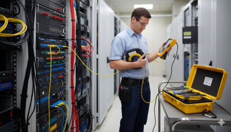
These wipes are manufactured from lint-free, non-abrasive materials. Standard paper towels or household tissues leave behind microscopic fibers that contaminate the splicing area. Conversely, professional cleaning wipes leave absolutely zero residue. When cleaning bare fiber, always pull the wipe from the base of the stripped area toward the bare tip in a single, continuous stroke. Never wipe backwards, as this redeposits contaminants onto the clean surface. By maintaining a clean workspace, technicians prevent optical return loss and ensure that their splices pass stringent optical time-domain reflectometer (OTDR) certification tests on the very first attempt.
Safety Regulations and Tool Maintenance Protocols
Operating high-speed cutting tools and handling microscopic glass fibers carries inherent physical risks. Consequently, compliance with international safety standards is mandatory for all field operations. For instance, the Occupational Safety and Health Administration (OSHA) outlines specific guidelines for hand tool safety and hazardous material handling in telecommunication spaces. First and foremost, technicians must always wear ANSI-approved protective eyewear during the cable preparation process. When pulling a longitudinal slitter, polymer shards or broken blades can fly off unpredictably. Eye protection prevents catastrophic vision injuries.
Furthermore, proper handling of cleaning chemicals is a critical safety pillar. Isopropyl alcohol (IPA) is highly flammable and volatile. Therefore, it must be stored in approved, spill-proof pump dispensers. Technicians must work in well-ventilated spaces to avoid inhaling concentrated vapors. Additionally, used cleaning wipes must be disposed of in designated fire-safe containers to prevent accidental ignition. When working inside dark utility vaults or confined spaces, proper ventilation and air quality monitoring are legally required to prevent suffocation or toxic exposure from accumulated ground gases.
Maintaining Your Fiber Optic Longitudinal Slitter Blades
To guarantee long-term performance and operator safety, establishing a strict maintenance routine is highly recommended. The cutting blades are the most critical wear components of your Fiber Optic Longitudinal Slitter. Over time, the abrasive polymers of the cable jacket will inevitably dull the blade edge. A dull blade requires more pulling force, which increases hand fatigue and raises the risk of tool slippage. Therefore, inspect your blades before every shift. Look for micro-chipping or dull spots under a magnifying glass. If you notice any resistance during test cuts, replace the blades immediately using genuine replacement parts from EPCOM.
In addition to blade inspection, keep the guide channels clean. Dirt, plastic shavings, and gel residue can accumulate inside the grooves. This accumulation prevents the cable from seating flat, which leads to inconsistent cutting depths. Clean the guide channels daily using a stiff-bristled brush and a small amount of cleaning solvent. After cleaning, apply a single drop of lightweight machine oil to the adjustment screws and spring hinges to prevent rust and ensure smooth operation. Store the slitter in a dry, padded carrying case when not in use to protect the delicate blades from physical impact during transport.
Common Troubleshooting Scenarios with a Fiber Optic Longitudinal Slitter
Even with high-quality tools and extensive training, technicians will occasionally encounter difficulties in the field. Consequently, having a troubleshooting plan is essential to keep projects on schedule. Let us examine some common issues faced during cable slitting and explain how to resolve them quickly and safely.
One common issue is uneven cutting depth along the cable length. This problem usually occurs when the cable is not kept perfectly straight during the pull. If the cable bends, the slitter tilted relative to the cable axis, causing one blade to cut deeper than the other. To resolve this, always use a cable straightener or guide frame when performing long cuts. Additionally, check if the guide channels are worn out. Over time, the internal walls of the channels can degrade, allowing the cable to wobble during the pull. If you notice structural wear, replace the slitter body immediately to maintain cutting precision.
Another frequent issue is difficulty in peeling the jacket after slitting. If the cut is too shallow, the remaining polymer layer will be too thick to tear open manually. To fix this, adjust the blade depth dial down in very small increments, usually around 0.05 millimeters. Perform another test cut and try peeling again. Conversely, if you cut too deep, you will notice score marks on the inner buffer tubes. This indicates a highly dangerous situation that can lead to micro-bending losses or fiber breakage. In this case, you must discard the damaged section of the cable, reset the blade depth to a shallower setting, and begin the preparation process again from a fresh starting point.
Finally, Fiber Optic Longitudinal Slitter blade binding or sticking during the pull can halt operations. This issue typically happens when slitting soft, rubbery jackets or cables filled with thick, sticky water-blocking gel. The gel can clog the blade channel, creating high friction that makes pulling difficult. To overcome this, clean the blade frequently during the cut. Squeeze a small amount of gel solvent onto the blade pathway to break down the sticky residue. For rubbery materials, applying a non-silicone lubricant to the guide grooves can significantly reduce friction, allowing the slitter to slide smoothly through the tough outer sheath.
Future Trends in Cable Tooling and EPCOM Innovations
The telecommunications industry is moving toward higher-density networks. Consequently, manufacturers are developing smaller, more packed cable structures, such as micro-sheaths and high-density ribbon cables. These ultra-compact designs contain thousands of fibers within an incredibly small footprint. This trend poses a significant challenge for traditional preparation tools, as the clearances between the outer jacket and the fragile internal fibers are shrinking. To meet these demands, EPCOM is continuously researching and developing next-generation tooling solutions.
Furthermore, future longitudinal slitters are incorporating smart, digital depth-control systems. Instead of manual adjustment dials, these advanced tools feature digital sensors that measure the precise jacket thickness in real-time. The tool then automatically adjusts the blade depth using micro-actuators as the cut progresses. This automation completely eliminates human error, guaranteeing perfect cuts on variable-thickness jackets. Additionally, advanced lightweight alloys and carbon-fiber composites are being utilized to construct lighter, more ergonomic tool bodies that reduce physical strain on field technicians.
Ultimately, the success of any optical network deployment depends on the quality of its installation tools. By combining a high-performance Fiber Optic Longitudinal Slitter with companion equipment like precision cleavers, fusion splicers, and premium cleaning wipes, field crews can conquer any installation challenge. As network speeds continue to accelerate worldwide, EPCOM remains committed to delivering the reliability, precision, and innovation that global telecommunication professionals trust to build the connected world of tomorrow.